nvidia-smi. At the command prompt, type nvidia-smi. 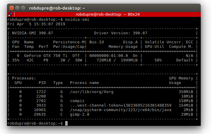
Hailo hardware acceleration. Check the HailoRT library is installed and seeing the Hailo-8 hardware. At the command prompt, type hailortcli fw-control identifyv2.4.0
This is the user manual for the VCAserver video analytics framework developed by VCA Technology. This manual describes how to set up and configure the video analytics to detect events of interest, whilst minimising false alerts.
VCAserver is available as a server application for Windows 11/Server or Ubuntu 22.04 (x86) and Ubuntu 22.04 (ARMv8).
See Getting Started for the essentials necessary to get VCAserver configured and start generating metadata.
This user guide documents each topic in detail, and each topic is accessible via the menu. However, to get started quickly, the essential topics are listed below.
Install or set up the platform on which VCAcore will run.
Learn how to navigate VCAcore’s interface.
If running VCAcore on the VCAbridge platform, configure the network and time settings by using the System Settings page.
Ensure that VCAcore is licensed for your required functionality by checking the Licensing page.
Create a video source.
Create some zones and detection rules. Calibrate the channel if necessary.
Create an action to send alerts to a third-party system.
Note that the default username and password for the VCAcore platform are:
Username: admin
Password: admin
Once the basic settings are configured, the following advanced topics may be relevant:
Set up classifiers by using the classification function.
Detect camera tampering or obscuration by using the tamper detect function.
Learn how the device detects gross scene changes with the scene change detection function.
Customise the annotation that is included in the video display, by using the burnt-in annotation settings.
Adjust advanced settings such as alarm hold off time, detection point and camera shake cancellation by using the advanced settings page.
For the purposes of this document, it is assumed that VCAserver will be installed on a dedicated hardware platform.
The hardware specifications for a given system will depend on the intended number of video channels to be processed, as well as which trackers and algorithms will be run on those channels. Some initial guidelines are provided below:
7.5 or higher or Hailo-8 AI AcceleratorAs the combinations of operating system, drivers and hardware is so variable, software requirements are based on configurations used internally for testing.
v535 or greaterHailo-8 drivers v4.21.0 (must be this exact version)HailoRT v4.21.0 (must be this exact version)v12.8 or higher should be installedTo ensure a host system is ready to run VCAserver, it is advised the following checks are made to ensuring the host system is ready to run the analytics.
nvidia-smi. At the command prompt, type nvidia-smi. Hailo hardware acceleration. Check the HailoRT library is installed and seeing the Hailo-8 hardware. At the command prompt, type hailortcli fw-control identifyExecuting on device: 0000:01:00.0
Identifying board
Control Protocol Version: 2
Firmware Version: 4.21.0 (release,app,extended context switch buffer)
Logger Version: 0
Board Name: Hailo-8
Device Architecture: HAILO8
Serial Number: <N/A>
Part Number: <N/A>
Product Name: <N/A>Installation instructions for the various platforms supported by VCAcore vary slightly and are outlined below.
VCAserver is installed as a service called VCA core and can be managed using the Windows service manager.
The configuration file for VCAcore is stored: C:\VCACore

The VCAserver MSI package installs the base analytics engine, interface and deep learning models.

The VCAserver installation can be modified to reconfigure the Web UI and the Recovery service ports. Navigate to Apps & Features within the Windows settings and select Modify on the VCA-Core entry.

Select Change, enter the desired ports and proceed through installation to apply the changes.

VCAserver is installed as a systemd service, as such when installation is complete the VCAcore service will be started automatically. The VCAcore service can be managed using the a systemd service manager, e.g. sudo systemctl restart vca-core.service
When installed the VCAserver configuration file is stored: /var/opt/VCA-Core/
VCAserver on Linux comes as a single archive file containing an .sh script, which handles the installation of the VCAcore components. Once the archive has been downloaded, navigate to folder and unpack the installation scripts from the archive:
VCA-Core-**VERSION_NUMBER**-vca_coreChange file attributes to allow the script to run. chmod +x ./VCA-Core-**VERSION_NUMBER**-vca_core (for example e.g. chmod +x ./VCA-Core-1.5.0-vca_core.sh)
Next run the .sh script: sudo ./VCA-Core-**VERSION_NUMBER**-vca_core, (for example e.g. sudo ./VCA-Core-1.5.0-vca_core.sh).

VCAserver should be installed as a system service. The install directory is fixed to /opt/VCA-Core/and will request desired ports for VCAserver’s manager and web servers. During install it is possible to run the Prebuild engines optimisation step. This runs the model optimisation step as part of the install, ensuring all models are ready to run when installation is finished. Depending on GPU configuration this could take a long time.

Important notes: VCAserver is developed and tested against Windows 10 and Ubuntu 18.04. Although the application may run on other versions of Windows or Linux, support is limited to this version only.
Periodically new versions of VCAserver will be released with new features, please check for software updates at the VCA Support page.
When upgrading VCAserver, backup the system configuration (System -> Configuration), uninstall or delete the existing VCAserver version and run the new installation packages as above.
When the upgrade is complete the configuration is persisted and upgraded to work with the new version.
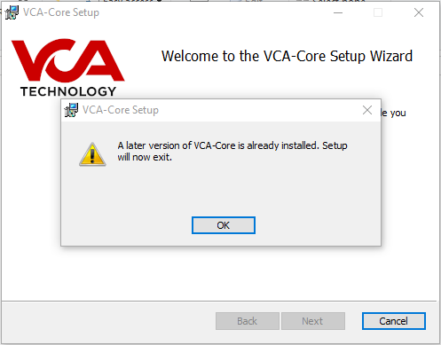
Downgrading to a previous version of VCAserver is not supported. If a previous version is required, the existing installation and configuration must be deleted before the desired version is installed. Windows systems will raise an error during install in this case.
VCAserver, on both Windows and Ubuntu, has a management service built in. This utility allows control of the VCAserver application via a Web UI to allow simple remote management.
The recovery service is always running and by default is accessible at: http://[HOST_COMPUTER_IP]:9090/.
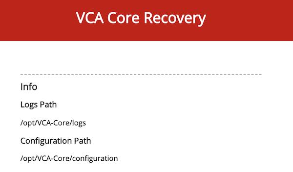
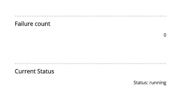
The recovery service provides a range of functionality.
Details of the logs and configuration locations for the currently running instance of VCAserver.
A failure count is provided which will keep track of the number of times the VCAcore application has restarted.
Lastly, the current status of the VCAserver application is also provided.
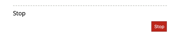
The main function of the VCAcore Service it to manage the VCAserver application. By default VCAserver is always running. To stop the application, press the Stop button which will allow the service to perform additional management tasks.
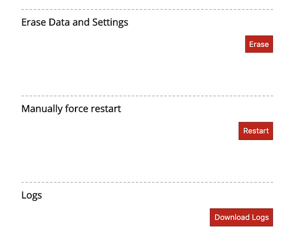
Once stopped, the VCAcore Service is able to erase data and settings, resetting the VCAserver application and configuration back to a default state. An option is also available to download the log files.
Lastly to restart the VCAserver application click the Restart button.
This topic provides a general overview of the VCAserver configuration user interface.
The VCA user interface features a persistent navigation bar displayed at the top of the window.

There are a number of elements in this navigation bar, each is described below:
 : The menu icon. Click the menu icon to access the Side Menu for convenient navigation through the application.
 : The view channels icon. Click the icon to access the View Channels page.
 : The configuration state icon. Displays the current saved state of the system. Changes to the system are saved and synchronised automatically, the configuration state icon indicates the current state of synchronisation. The configuration state can be in one of two states:
: All configuration changes have been successfully synchronized between the web interface and the system.
: The configuration state icon. Displays the current saved state of the system. Changes to the system are saved and synchronised automatically, the configuration state icon indicates the current state of synchronisation. The configuration state can be in one of two states:
: All configuration changes have been successfully synchronized between the web interface and the system. : The configuration is currently being synchronised between the web interface and the system.
 : The language icon. Click to change the UI language.
 : The settings icon. Click to access the Settings Page.
 : The arm/disarm icon. Click to change the Arm/Disarm State of the device.
Clicking the icon displays the side navigation menu:
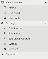
Every page in the VCA user interface is accessible through the side menu. The ![]() icon next to a menu item indicates that the item has sub-items and can be expanded.
icon next to a menu item indicates that the item has sub-items and can be expanded.
Items in the side menu are automatically expanded to reflect the current location within the web application.
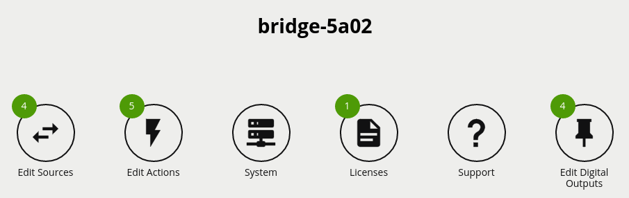
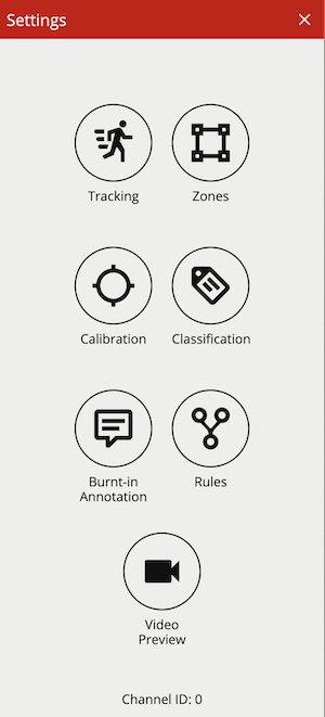
The settings page displays a number of links to various configuration pages:
To create sources and take advantage of the VCAserver analytics, each channel will require a license. There are a number of different license types available, a Video Source can be assigned a specific license type based on the required features.
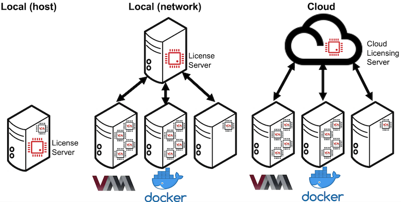
Licensing is either managed by a License Server or via Cloud Licensing. A License Server is user managed, and supports perpetual and evaluation license solutions both on the host system running VCAserver or across the network. Cloud Licensing is an externally managed service, allowing for subscription based licensing models, requiring VCAserver to have a active internet connection.
To manage licensing, navigate to the license settings page. This interface allows the user to define which licensing Method to use and the settings associated with each.
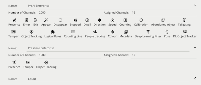
Both methods expose a pool of available licenses which VCAserver can use with configured Video Sources. A pool of licenses can be made up of a range of different license packs with different license types and available amounts. For each license pack, the total number of channels and the currently assigned channels is provided. The assigned channels takes into account all instances of VCAserver using a license from this pack. Additionally, the features available to the license type are also shown.
When a license is assigned, it cannot be used by another channel or instance of VCAserver. Both the License Server and Cloud Licensing manage multiple instances of VCAserver using licenses simultaneously.
The licensing Method can be switched from Cloud to Local (or vice-versa) at any time:
Click the Method bar to cycle between Cloud and Local.
Check connection settings and click Connect.
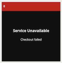
VCAserver will attempt to assign the same licenses to configured Video Sources, if available. If for any reason the previously configured license is not available, a checkout failed message will be see in the View Channels Page.
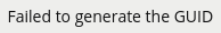
A License Server links perpetual license packs to a Hardware GUID, which is a unique identifier specific to the physical hardware the License Server is running on. The License Server generates the Hardware GUID only on physical (non-virtualised) systems. On virtualised systems a Hardware GUID will not be available and the following message displayed.
Once a VCAserver is connected to a License Server, the license pool associated with that License Server will be shown. The License Server will either be running:
Local (host): where the License Server and VCAserver are running on a single physical hardware device.
Local (network): where instances of VCAserver, either running on physical hardware or virtualised, connect to a License Server (running on physical hardware) across the network. All licenses will be validated against the License Server’s Hardware GUID.
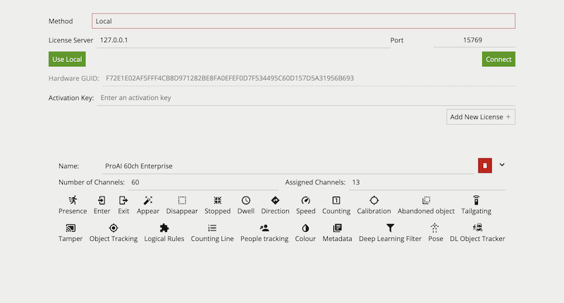
To configure the License Server settings the following options are provided:
License Server: The address of the License Server. For Local (host) this will be set to 127.0.0.1, when Local (network) a network address will need to be specified where an instance of the License Server is running.
Port: The port the License Server is using. Default is 15769 (protocol TCP). In cases where a network configuration is required this port will need to be open between the VCAserver and License Server.
Use Local: Sets license server to 127.0.0.1 and connects.
Connect: Connects this instance of VCAserver to the License Server at the provided address.
Hardware GUID: The unique code for the hardware where the License Server is running. Required to generate an activation key. If no License Server is running at the provided address, this will be blank.
Activation Key: Enter an activation key to add licenses to the License Server’s license pool.
The list of installed licenses and their features are displayed underneath.
The Activation Key field allows an Activation Token to be entered. (requires the system accessing the Licensing Settings page to be connected to the internet):
Enter the Activation Token and click Add New License.
A web request is sent to an activation server including the activation token, Hardware GUID and other system specific information.
When complete a validated Activation Key for this Hardware GUID is returned and applied, verify the new license, of the correct license type, appears below with the required features available.
Note: If offline activation is required, please contact your reseller
On new installations, before a user is able to add sources, the License Server will need a license added to the license pool.
In the case of an upgrade, or on systems that have run the License Server before, the system will persist the licenses already in the pool.
Licenses can also be deleted from the License Server’s pool (in the case of expired evaluation licenses):
Click red delete button next to license type.
A warning will be displayed asking for confirmation, Video Sources that make use of the license pack to be deleted may stop working.
An evaluation license provides the same functionality as a perpetual license type, but for a fixed period. They are added, managed and assigned to a channel in the same way as a perpetual license. They are denoted in the interface with an Evaluation flag and a Days Remaining count.
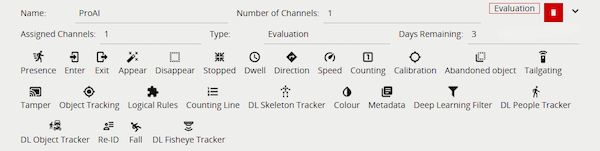
A channel assigned an evaluation license, with less than 14 days remaining, will start to show a warning message Burnt-in Annotation in the View Channels Page. When the Days Remaining runs out the channel will stop processing and no metadata or events will be generated.
The License Server used by VCAserver can be switched at any time:
Enter a new address in the License Server field and click Connect or, click Use Local to reset to the License Server on the host system, if available.
VCAserver will attempt to assign the same licenses to configured Video Sources, if available. If for any reason the previously configured license is not available, a checkout failed message will be see in the View Channels Page.
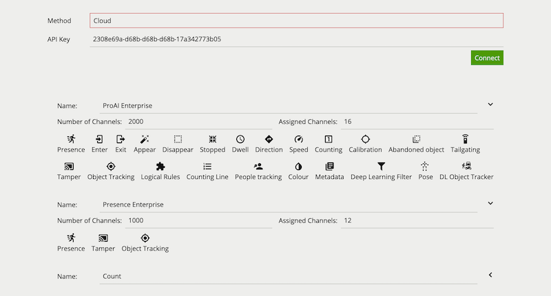
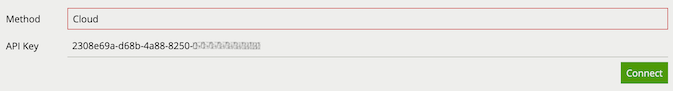
Once a valid API Key is provided and the connection to the Cloud Licensing Server is established, the license pool associated with that API key will be shown.
When using Cloud Licensing the license pool available to VCAserver is managed using a cloud portal.
Method: Switches between Cloud Licensing or a License Server.
API Key: An authorisation token that links to a Cloud Licensing Account.
Connect: Connects this instance of VCAserver to the Cloud Licensing Servers.
The list of installed licenses and their features are displayed underneath.
On new installations, before a user is able to add sources, the Cloud Licensing account will need a license added to the license pool.
VCAserver will lose connection to its Licensing method in certain situations:
VCAserver has a 5 day grace period, allowing the analytics to continue to process in the absence of a License method. Additionally, an action can be configured to generate an event in this situation. After this time, analytics will stop processing and no events or metadata will be generated.
When VCAserver’s connection to a License Server or Cloud Licensing is re-established, and the license pool of the License Server or Cloud Licensing has not changed, VCAserver will reconnect and checkout licenses for the channels that were using them previously.
If the license pool has changed during the downtime, or if a configuration is imported to VCAserver which specifies a different License Server or Cloud Licensing account, with a different license pool, VCAserver will attempt to assign licenses to configured Video Sources, if available. If for any reason a previously configured license is not available, a checkout failed message will be see in the View Channels Page, and a review of the Video Sources may be required to ensure that all channels are correctly licensed.
If a different License method is to be used, or if a configuration is imported to VCAserver which specifies a License method that is no longer available, then follow the guide lines for Switching License Method
For more information on the complete range of additional features available, please visit VCA Technology
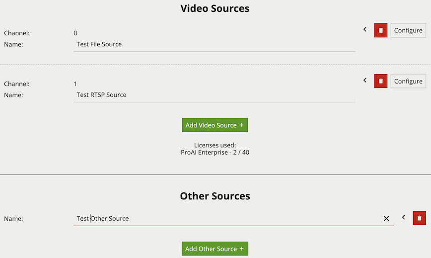
Sources are user configured inputs to VCAserver, which include video sources and non-video sources (e.g. digital inputs). The Edit Sources page allows users to add/remove sources and configure existing sources.
Common Properties:
More detailed information can be seen for each Source by clicking the ![]()
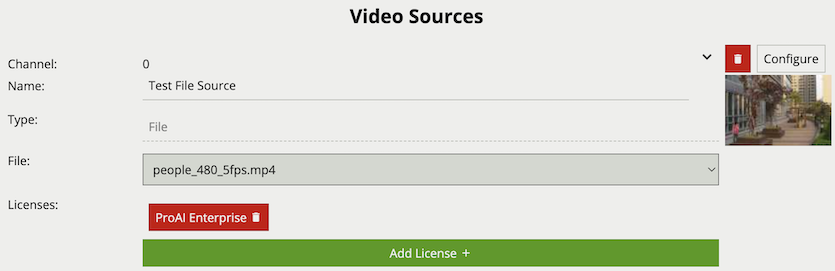
Video sources are automatically linked with a channel when added. A preview is provided of the video source showing snapshots of the video content or any warnings. The number of video sources which can be added to the system is dependant on the user’s license. A list of the currently available license types (e.g. Pro) and the number of those licenses used is provided (e.g. 2 / 16).
License selection allows for a specific license type to be associated with a channel. Licenses can be changed on a video source at any time. However, once a channel is configured with rules and functions linked to a particular license type, changing the license type for that channel is not advised.
File sources enable the streaming of video from a file located in a test-clips folder on the host machine. The folder is in a subdirectory of the default data location:
/var/opt/VCA-Core/test-clips/C:\VCACore\test-clips\Any video files located in this folder will be presented in the File drop down menu. Please note that when files are added to this folder, the web interface will need to be refreshed for the UI to see the files in the drop down menu.
Properties:
The RTSP source streams video from remote RTSP and RTSPS servers such as IP cameras and encoders. The minimum frame rate required for good quality tracking is 15fps. The suggested resolution for these RTSP streams is 480p or greater.
The Discover Sources tool can be used to detect and add RTSP sources from ONVIF compliant devices, such as IP cameras and Encoders, or other instances of VCAserver with ONVIF enabled.
Note: resolutions greater than 480p will result in greater CPU resource usage and may not always result in greater tracking accuracy.
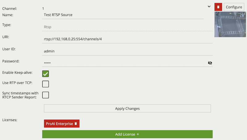
Properties:
When using an RTSPS URI, e.g. rtsps://192.168.0.25:8554/channels/0, additional TLS Validation option properties are provided.
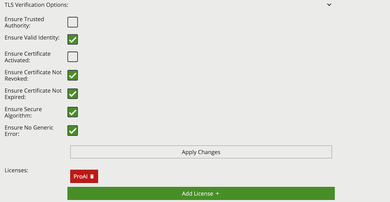
Common Name property of the SSL certificate.The range of video codecs supported by VCAserver is given below:
Note: where supported, the following H.264 profiles can be decoded using hardware acceleration: ConstrainedBaseline, Main, High, MultiviewHigh and StereoHigh
When using an RTSP stream as a source please ensure it is encoded with one of the supported compression formats. Likewise, when using a file as a source please note that VCAserver is compatible with many video file containers (.mp4, .avi etc.) but the video file itself must be encoded with one of the above supported compression formats.
The Discover Sources tool provides a way to scan for ONVIF complaint devices broadcasting valid video streams, and add those streams as a RTSP video source.
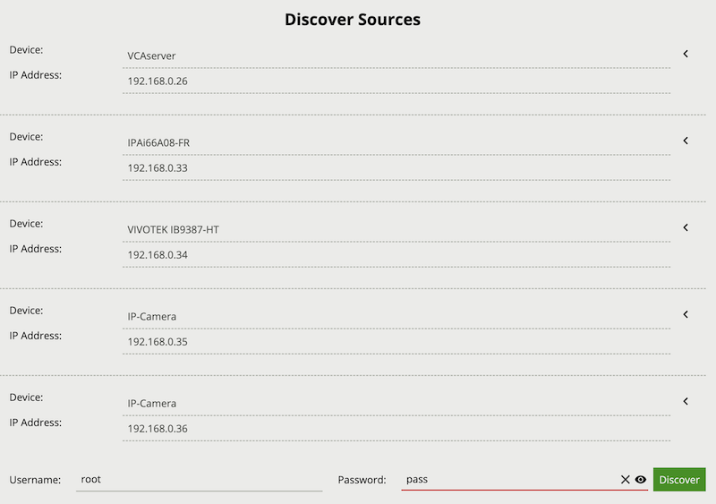
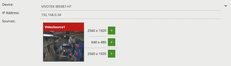
To initiate a Discover Sources scan press the Discover button. Any device broadcasting compliant ONVIF discovery information will be listed as a Device with an IP Address. If the correct username and password are provided when initiating the scan, then these will be used to authenticate with the discovered devices. Available video sources and associated media profiles will be visible when pressing the drop down arrow. The desired video source media profile can then be added as a RTSP source by pressing the Plus icon.
If the provided username and password are not correct, then an Authentication Required message will be displayed.
Various non-video sources are available to the user. Once added, these sources can then be assigned to Actions and, in certain cases, referenced in the Rules.
Interval sources can be used to generate events periodically, e.g. a heartbeat to check that the device is still running.
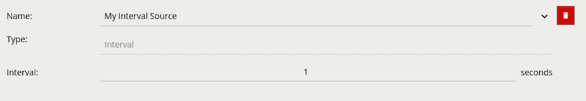
Properties:
If digital input hardware is available, these will show in the list of other sources.
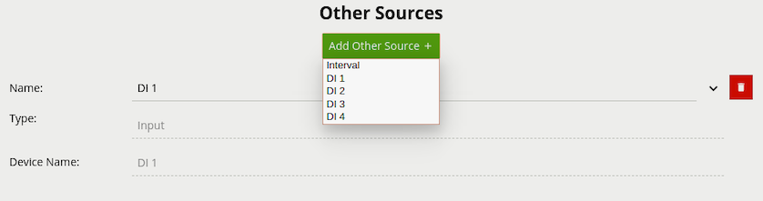
Properties:
The Armed source generates an event when the system becomes armed.
The Disarmed source generates an event when the system becomes disarmed. Note that any actions that this source is assigned to must be set to Always Trigger, otherwise the action will not be triggered due to the system being disarmed.
The License source generates an event in the following scenarios:
Events will be generated and actions will be fired continuously at the defined interval.
The Event type token (e.g. {{type.string}}) can be used to identify the type of connection event being generated.
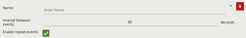
Properties:
The HTTP source creates an arbitrary REST API endpoint with a state variable that can be set true or false. This creates a virtual Digital Input which third party systems can enable or disable. The HTTP source can be referenced by the [Source Filter] in a rule graph.
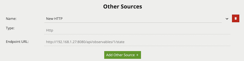
Properties:
The Schedule source allows the definition of a schedule of time when the source is either on or off. The Schedule other source can be referenced by the [Source Filter] in a rule graph. Additionally, the schedule source can be used to directly control the armed state of VCAserver.
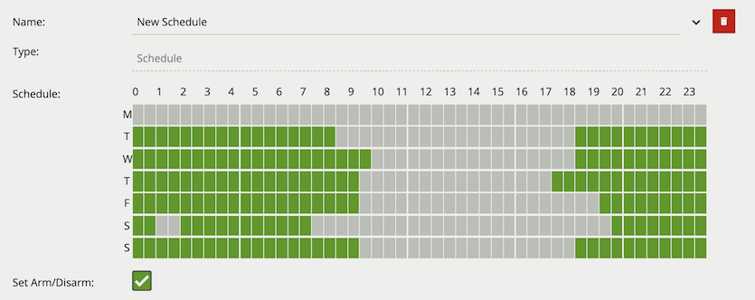
Properties:
on periods (in green) and off periods (in grey). Each row represents one of the seven days in a week and each column represents a half hour period in that 24 hours.The System source generates an event when the selected system resource goes above the user defined threshold. The source can be configured to continue to send events, whilst the resource remains above the threshold, at a set interval or to send a single event each time the threshold is reached.
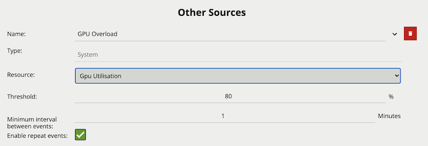
Properties:
The View Channels page displays a preview of each configured channel along with any event messages.
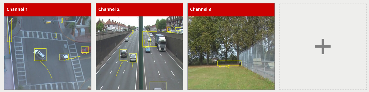
Click a thumbnail to view the channel and configure VCAserver related settings. Click the plus icon to go to the add video source page.
After clicking on a channel, a full view of the channel’s video stream is displayed along with any configured zones, counters and rules and the channel settings menu open.
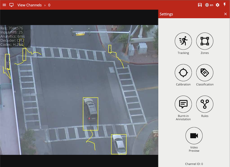
If the settings menu is closed, a tab with a icon is displayed on the right hand side of the page. Click this to reopen the channel settings menu.
This menu contains various useful links for configuring various aspects of the channel:
VCAserver supports a number of tracker technologies for use with a configured channel of video. The available trackers are listed below:
Under the Trackers menu item is a drop down menu option for Tracking Engine; under which, one of the available trackers can be selected.
![]()
When a tracker is selected by the user, an initialisation phase will be required. This will vary based on the selected tracker.
![]()
![]()
Once initialised, VCAserver will begin analysing the video stream with the selected tracker. Settings specific to that tracker will also be displayed below the tracker engine selection option.
Regardless of the tracker selected, any tracked object can be passed through the available rules. However, in some cases, certain rules or algorithms will only be available with a specific tracker. For example, the abandoned and removed object rules are only available with the Object Tracker.
Some settings are universal across all trackers, these are outlined below:
The Loss Of Signal Emit Interval defines the amount of time between emissions when a channel loses signal to it’s source.
The default setting is 1 second.
![]()
The Tamper Detection module is intended to detect camera tampering events such as bagging, de-focusing and moving the camera. This is achieved by detecting large persistent changes in the image.
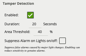
To enable tamper detection click the Enabled checkbox.
In the advanced tamper detection settings, it is possible to change the thresholds for the area of the image which must be changed and the length of time it must be changed for before the tamper event is triggered.
If false alarms are a problem, the duration and/or area should be increased, so that large transient changes such as close objects temporarily obscuring the camera do not cause false alarms.
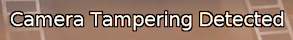
When a tamper event is detected, a tamper event is generated. This event is transmitted through any output elements as well as being displayed in the video stream:
Calibration filtering is a tool preventing very large or very small objects from being tracked and causing false alarms.
![]()
![]()
In the above example; a small object with an estimated height of 0.3m and area of 0.3sqm is removed by the calibration filter.
This can also improve situations where large motion is detected in the Object Tracker caused by lighting changes, or a Deep Learning Tracker recognising very large or small features as a valid object. An object is defined as large or small based on the metadata produced when Calibration is enabled. When Calibration Filtering is enabled an object is valid when it meets all of the following criteria:
0.5m6m0.5sqm50sqmIf any of the above criteria is not met, the object will no longer appear as a tracked object. Filtered Objects can be visualised using the Burnt-In-Annotations.
![]()
To enable calibration filtering click the Enabled checkbox. Calibration must be enabled on the channel and properly configured to ensure valid objects are not removed.
The Object Tracker is a motion based detection engine. Based on changes detected in the image, the algorithm separates the image into foreground and background, tracking any foreground object that is moving above a set threshold. The Object Tracker has the following settings:
Enables the Deep Learning Classifier to analyse any detected objects.
![]()
The default setting is off.
The Stationary Object Hold-on Time defines the amount of time an object will be tracked by the engine once it becomes stationary. Since objects which become stationary must be “merged” into the scene after some finite time, the tracking engine will forget about objects that have become stationary after the Stationary Object Hold-on Time.
![]()
The default setting is 60 seconds.
This threshold amount of time an object must be classed as abandoned or removed before an Abandoned / Removed rule will trigger.
![]()
The default setting is 5 seconds.
The Minimum and Maximum Tracked Object Size defines the size limits of the object that will be considered for tracking.
For most applications, the default settings are recommended. In some situations, where more specificity is required, the value can be manually specified. Changing these values allow the engine to track smaller and larger objects, which it may increase the susceptibility to false detections.
![]()
The Object Tracker Sensitivity value allows the object tracker to be tuned to ignore movement below a certain threshold. Combined with the foreground pixels burnt in annotation, which visualises the area of the scene the object tracker is detecting movement, this value can be adjusted to filter out environmental noise.
![]()
The default setting is Medium High.
Learn more about Scene Change Detection.
For every tracked object, a point is used to determine the object’s position, and evaluate whether it intersects a zone and triggers a rule. This point is called the detection point.
There are 3 modes that define the detection point relative to the object:
In automatic mode, the detection point is automatically set based on how the channel is configured. It selects ‘Centroid’ if the camera is calibrated overhead, or ‘Mid-bottom’ if the camera is calibrated side-on or not calibrated.
![]()
In this mode, the detection point is forced to be the centroid of the object.
![]()
![]()
In this mode, the detection point is forced to be the middle of the bottom edge of the tracked object. Normally this is the ground contact point of the object (where the object intersects the ground plane).
![]()
![]()
Learn more about Tamper Detection.
Learn more about Calibration Filtering.
See Loss Of Signal Emit Interval.
The Deep Learning People tracker tracks people in dense and busy scenes.
The Deep Learning People Tracker is based on the detection of a person’s head and shoulders, providing the location of a person in the field of view even when large parts of their body are occluded. See Deep Learning Requirements for hardware requirements for this algorithm.
The Deep Learning People Tracker has the following settings:
Learn more about Tamper Detection.
Learn more about Calibration Filtering.
See Loss Of Signal Emit Interval.
The Deep Learning Skeleton tracker tracks people in situations where the camera field of view is relatively close.
The Deep Learning Skeleton Tracker is based on Pose Estimation technology, providing the location of a person in the field of view as well as additional key point metadata on the parts of the body. See Deep Learning Requirements for hardware requirements for this algorithm.
The Deep Learning Skeleton Tracker has the following settings:
Learn more about Tamper Detection.
Learn more about Calibration Filtering.
See Loss Of Signal Emit Interval.
The Deep Learning Object Tracker is designed for accurate detection and tracking of people, vehicles and key objects in challenging environments where motion based tracking methods would struggle. The list of objects detected by the Deep Learning Object Tracker is given below:
| Class Name | Description |
|---|---|
person |
A person, or tracked object with a person present (e.g bicycle) |
motorcycle |
A motorcycle |
bicycle |
A bicycle |
bus |
A bus |
car |
A car |
van |
A van, including mini-vans and mini-buses |
truck |
A truck, including lorries / commercial work vehicles and bus / coaches |
forklift |
A forklift truck |
bag |
A backpack or holdall |
The Deep Learning Object Tracker is based on a classification and detection model, providing the location of an object in the field of view. See Deep Learning Requirements for hardware requirements for this algorithm.
The Deep Learning Object Tracker has the following settings:
Optical Flow is a motion detection algorithm. It works in addition to the standard motion detection algorithm and helps reduce false positives from stationary objects. Enabling will have an additional CPU resource load.
![]()
In addition to the Stationary Hold On Time, an additional setting Require Initial Movement, is available which will prevent objects which have not moved from being tracked.
![]()
See Detection Point of Tracked Objects.
Learn more about Tamper Detection.
Learn more about Calibration Filtering.
See Loss Of Signal Emit Interval.
The Deep Learning Thermal Tracker is designed for accurate detection and tracking of people and vehicles in thermal camera views. The list of objects detected by the Deep Learning Thermal Tracker is given below:
| Class Name | Description |
|---|---|
person |
A person |
vehicle |
A vehicle (car, van, truck, bus) |
The Deep Learning Thermal Tracker is based on a classification and detection model, providing the location of an object in the field of view. See Deep Learning Requirements for hardware requirements for this algorithm.
The Deep Learning Thermal Tracker has the following settings:
In addition to the Stationary Hold On Time, an additional setting Require Initial Movement, is available which will prevent objects which have not moved from being tracked.
![]()
See Detection Point of Tracked Objects.
Learn more about Tamper Detection.
Learn more about Calibration Filtering.
See Loss Of Signal Emit Interval.
The Deep Learning Fisheye Tracker tracks people in fisheye camera views.
Note: The Deep Learning Fisheye Tracker only works on fisheye video streams which have not been dewarped.
The Deep Learning Fisheye Tracker uses a deep learning segmentation method, providing the location of a person in the field of view even when large parts of their body are occluded. See Deep Learning Requirements for hardware requirements for this algorithm.
The Deep Learning Fisheye Tracker has the following settings:
In addition to the Stationary Hold On Time, an additional setting Require Initial Movement, is available which will prevent objects which have not moved from being tracked.
![]()
See Detection Point of Tracked Objects.
Learn more about Tamper Detection.
Learn more about Calibration Filtering.
See Loss Of Signal Emit Interval.
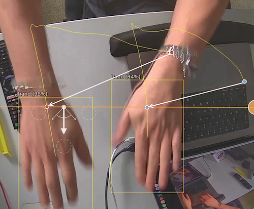
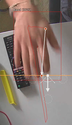
The Hand Object Interaction (HOI) Tracker is designed for the detection of hands, and the objects they hold. The HOI tracker requires a top down and relatively close field of view to detect optimally. The list of objects detected by the Hand Object Interaction Tracker is given below:
| Class Name | Description |
|---|---|
hand |
A hand |
object |
An object being held by a hand object |
person |
A person |
The Hand Object Interaction Tracker is based on a classification and detection model, providing the location of an object in the field of view. See Deep Learning Requirements for hardware requirements for this algorithm.
The Hand Object Interaction Tracker has the following settings:
See Detection Point of Tracked Objects.
Learn more about Tamper Detection.
Learn more about Calibration Filtering.
See Loss Of Signal Emit Interval.
Zones are the detection areas on which VCAserver rules operate. In order to detect a specific behaviour, a zone must be configured to specify the area where a rule applies.
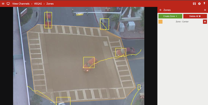
Zones can be added in multiple ways:
Right-clicking or tap-holding (on mobile devices) displays a context menu which contains commands specific to the current context.
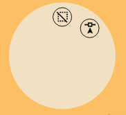
The possible actions from the context menu are:
To change the position of a zone, click and drag the zone to a new position. To change the shape of a zone, drag the nodes to create the required shape. New nodes can be added by double-clicking on the edge of the zone or clicking the add node icon ![]() from the context menu.
from the context menu.
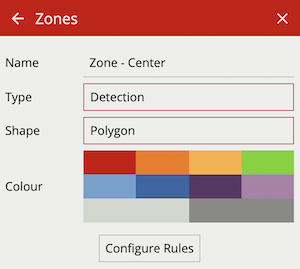
The zone configuration menu contains a range of zone-specific configuration parameters:
Zones can be deleted in the following ways:
VCAserver’s rules are used to detect specific events in a video stream. There are three rule types which can be utilised to detect events and trigger actions:
Basic Inputs / Rule: An algorithm that will trigger when a particular behaviour or event has been observed. E.g. Presence. Basic inputs can be used to trigger an action.
Filters: A filter will trigger if the object which has triggered the input rule meets the filter requirements. E.g. is moving as a specific speed. Filters can be used to trigger an action.
Conditional Rule: A logical link between one or more inputs to allow the detection of more complex behaviours. E.g. AND. Conditional rules can be used to trigger an action.
Within VCAserver, rule configurations can be as simple as individual basic inputs attached to a zone used to trigger an action. Alternatively rules can be combined into more complex logical rule configurations using conditional rules and filters. The overarching goal of the rules in VCAserver is to help eliminate erroneous alerts being generated, by providing functions to prevent unwanted behaviour from triggering an action.
More detail on the differences between these concepts is outlined below:
A basic input or rule can only be used to trigger an action or as an input to another rule type. Basic inputs always require a zone, and potentially some additional parameters. A basic input can be used on its own to trigger an action, although they are often used as an input to other filters or conditional rules.
The complete list of basic inputs are:
A filter cannot trigger an action on its own as it requires another basic input, filter or conditional rule to trigger. An example of this is the Object rule.
The complete list of filters are:
A conditional input, like a filter, is one that cannot trigger an action on its own. It requires the input of another basic input, conditional rule or filter to be meaningful. An example of this is the AND rule. The AND rule requires two inputs to compare in order to function.
The complete list of conditional rules are:
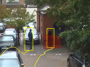
As rules are configured they are applied to the channel in real time allowing feedback on how they work. Objects which have triggered a rule are annotated with a bounding box and a trail. Objects can be rendered in two states:
Non-alarmed: Default rendered in yellow. A detected object which does not meet any criteria to trigger a rule and raise an event.
Alarmed: Default rendered in red. A detected object which has triggered one or more rules. Causes an event to be raised.
As seen below, when an event is raised, the default settings render details of the event in the lower half of the video stream. Object class annotations in this example are generated through calibrated classification
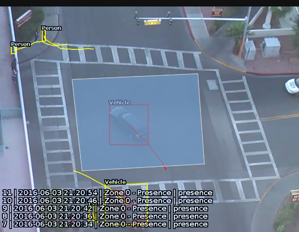
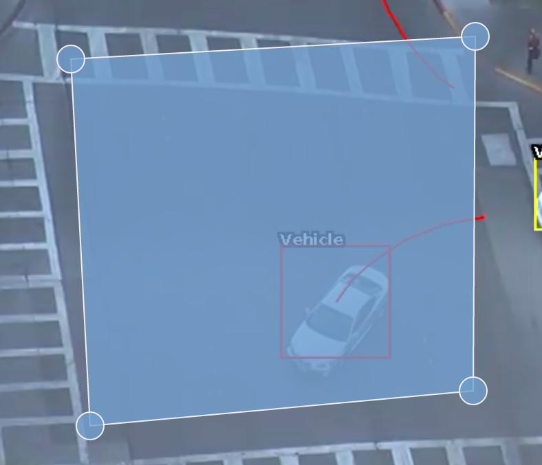
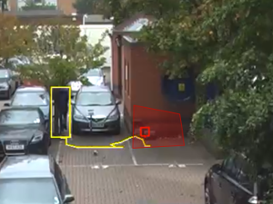
The trail shows the history of where the object has been. Depending on the calibration the trail can be drawn from the centroid or the mid-bottom point of the object. (See Detection Point of Tracked Objects for more information).
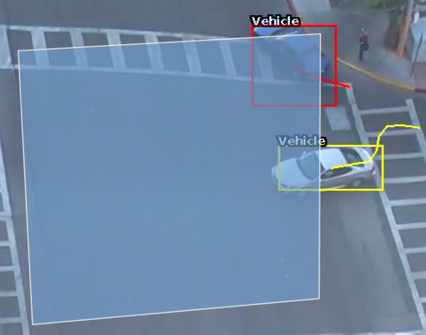
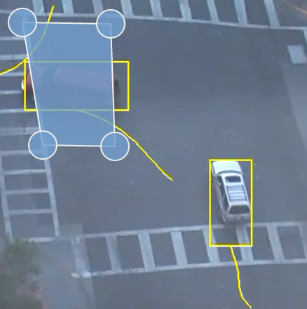
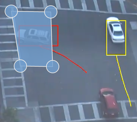
The trail is important for determining how a rule is triggered. The intersection of the trail point with a zone or line determines whether a rule is triggered or not. The following image illustrates this point: the blue vehicle’s trail intersects with the detection zone and is rendered in red. Conversely, while the white vehicle intersects the detection zone, its trail does not (yet) intersect and hence it has not triggered the rule and is rendered in yellow.
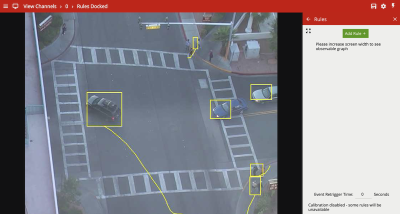
Rules are configured on a per channel basis by opening the rules menu when viewing the channel. Configuration is possible in two forms: the docked mode, in which both the rules and the video stream are visible or expanded view, in which a graph representation is provided to visualise the way the rules are connected.
The rules page opens in the ‘docked’ mode, alongside the live video stream.
The user may click on the expand button to switch to the expanded view. Please note that the rules graph is only visible in the expanded view.
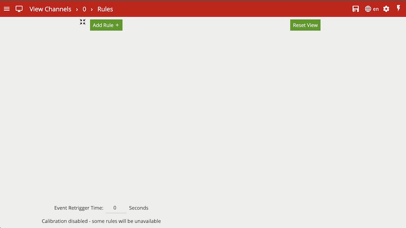
In the expanded view, the user can add rules, and use the Rules Editor to connect the rules to one another. The graph on the right hand side updates in real time to reflect the user’s changes.
The Event Retrigger Time allows the specification of a period of time in which a rule, triggered by the same object, can not generate multiple events. This prevents scenarios where an object crossing the boundary of zone multiple times within the period, could trigger a configured rule repeatedly.
This setting takes into account the object triggering the rule, ensuring events from new objects triggering the same rule are not suppressed. Only rules with can trigger actions enabled will be impacted by this setting.
The first steps to defining a rule configuration is to add the basic inputs, configure the respective parameters and link to a zone. Click the  button and select the desired rule from the drop menu.
To delete a rule click the corresponding delete icon ![]() . Please note rules of any type cannot be deleted if they serve as an input to another rule. In this case the other rule must be deleted first.
. Please note rules of any type cannot be deleted if they serve as an input to another rule. In this case the other rule must be deleted first.
Below are the currently supported basic inputs, along with a detailed description of each.
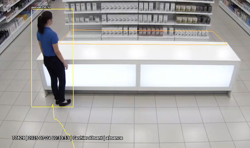
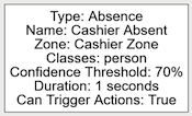
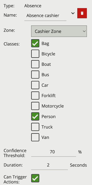
The absence rule detects when a zone has not contained an object of a defined class for a set duration. If other objects are present, of a class not defined, the rule will still trigger.
The following image illustrates the empty zone which has been absent of a person object for two seconds.
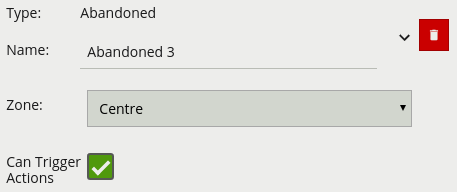
| Property | Description | Default Value |
|---|---|---|
| Name | A user-specified name for this rule | “Absence #” |
| Can Trigger Actions | Specifies whether events generated by this rule trigger actions | Active |
| Zone | The zone this rule is associated with | None |
| Duration | Period of time the zone must have been empty before the rule triggers | 1 seconds |
| Classes | The object classes allowed to trigger an alert | None |
| Confidence Threshold | The algorithm confidence (as a percentage) required to trigger the rule | 70 |
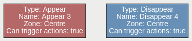
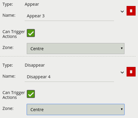
The appear rule detects objects that start being tracked within a zone, e.g. a person who appears in the scene from a doorway.
Conversely, the disappear rule detects objects that stop being tracked within a zone, e.g. a person who exits the scene through a doorway.
Note: The appear and disappear rules differ from the enter and exit rules as detailed in the enter and exit rule descriptions.
| Property | Description | Default Value |
|---|---|---|
| Name | A user-specified name for this rule | “Appear #” |
| Can Trigger Actions | Specifies whether events generated by this rule trigger actions | Active |
| Zone | The zone this rule is associated with | None |
| Property | Description | Default Value |
|---|---|---|
| Name | A user-specified name for this rule | “Disappear #” |
| Can Trigger Actions | Specifies whether events generated by this rule trigger actions | Active |
| Zone | The zone this rule is associated with | None |
The direction rule detects objects moving in a specific direction. Configure the direction and acceptance angle by moving the arrows on the direction control widget. The primary direction is indicated by the large central arrow. The acceptance angle is the angle between the two smaller arrows.
Objects that travel in the configured direction (within the limits of the acceptance angle), through a zone or over a line, trigger the rule and raise an event.
The following image illustrates how the white car, moving in the configured direction, triggers the rule whereas the other objects do not.
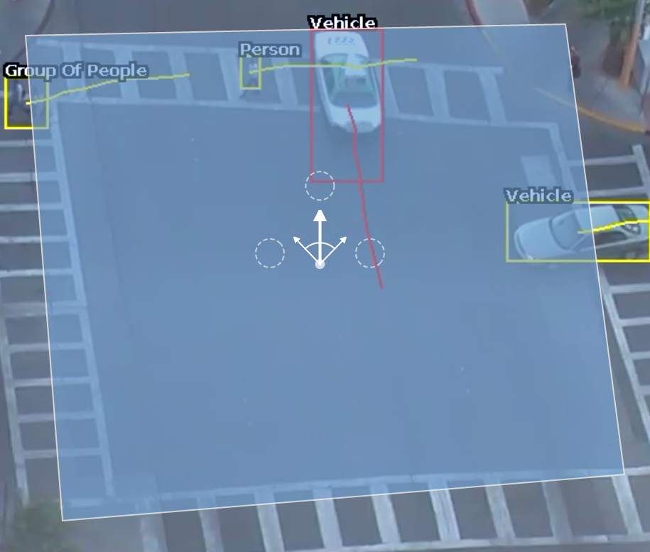
Note: Direction is calculated as the vector between, the the oldest history point of a tracked object (the end of the yellow tail) and the point of intersection of a zone/line. This can lead to some unexpected behaviour, see the two examples below:
The Directional Crossing rule would avoid both of these scenarios.
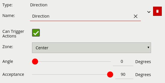
| Property | Description | Default Value |
|---|---|---|
| Name | A user-specified name for this rule | “Direction #” |
| Can Trigger Actions | Specifies whether events generated by this rule trigger actions | Active |
| Zone | The zone this rule is associated with | None |
| Angle | Primary direction angle, 0 - 359. 0 references up. | 0 |
| Acceptance | Allowed variance each side of primary direction that will still trigger rule | 0 |
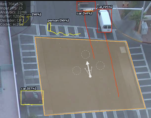
The directional crossing rule is designed to reduce false alarms common with simple line crossing use cases. Directional Crossing is designed for use with a zone rather than a line, and adds a number of additional checks for an object as it enters as well as exits that zone.
For an object to trigger the Directional Crossing rule it must:
Configure the direction and acceptance angle by moving the arrows on the direction control widget. The primary direction is indicated by the large central arrow. The acceptance angle is the angle between the two smaller arrows.
The following image illustrates how the white car, moving in the configured direction, triggers the rule whereas the other objects do not.
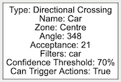
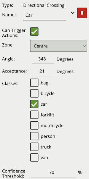
| Property | Description | Default Value |
|---|---|---|
| Name | A user-specified name for this rule | “Directional #” |
| Can Trigger Actions | Specifies whether events generated by this rule trigger actions | Active |
| Zone | The zone this rule is associated with | None |
| Angle | Primary direction angle, 0 - 359. 0 references up. | 0 |
| Acceptance | Allowed variance each side of primary direction that will still trigger rule | 0 |
| Classes | The object classes allowed to trigger an alert | None |
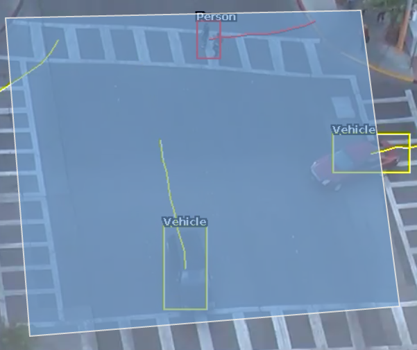
A dwell rule triggers when an object has remained in a zone for a specified amount of time. The interval parameter the time the object has to remain in the zone before an event is triggered.
The following image illustrates how the person, detected in the zone, is highlighted red as they have dwelt in the zone for the desired period of time. The two vehicles have not been present in the zone for long enough yet to trigger the dwell rule.
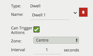
| Property | Description | Default Value |
|---|---|---|
| Name | A user-specified name for this rule | “Dwell #” |
| Can Trigger Actions | Specifies whether events generated by this rule trigger actions | Active |
| Zone | The zone this rule is associated with | None |
| Interval | Period of time in seconds | 1 |
The enter rule detects when objects enter a zone. In other words, when objects cross from the outside of a zone to the inside of a zone.
Conversely, the exit rule detects when an object leaves a zone: when it crosses the border of a zone from the inside to the outside.
Note: Enter and exit rules differ from appear and disappear rules, as follows:
Whereas the enter rule detects already-tracked objects crossing the zone border from outside to inside, the appear rule detects objects which start being tracked within a zone (e.g. appear in the scene through a door).
Whereas the exit rule detects already-tracked objects crossing the zone border from inside to outside, the disappear rule detects objects which stop being tracked within the zone (e.g. leave the scene through a door).
| Property | Description | Default Value |
|---|---|---|
| Name | A user-specified name for this rule | “Enter #” |
| Can Trigger Actions | Specifies whether events generated by this rule trigger actions | Active |
| Zone | The zone this rule is associated with | None |
| Property | Description | Default Value |
|---|---|---|
| Name | A user-specified name for this rule | “Exit #” |
| Can Trigger Actions | Specifies whether events generated by this rule trigger actions | Active |
| Zone | The zone this rule is associated with | None |
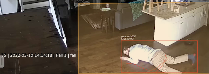
The Fall rule detects when a object classified as a Person, by either the Deep Learning People Tracker, Deep Learning Skeleton Tracker or Deep Learning Object Tracker, is in the fallen state.
When the Fall rule is added to a channel configuration, the fall detection algorithm begins to run on any object detected as person, which will have a GPU overhead proportional to the number of people detected in the scene.
Fall detection accuracy is reliant on continuing to track a person in the unusual orientations brought about by a fall. As such, it is advised to use the Deep Learning Skeleton Tracker, as it is better able to detect and track people in this fallen state. Interruptions in tracking a fallen person, will prevent the fall detection algorithm running whilst they are in that fallen state, and could result in missed events.
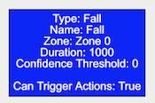
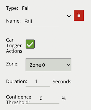
| Property | Description | Default Value |
|---|---|---|
| Name | A user-specified name for this rule | “Fall #” |
| Zone | The zone this rule is associated with | None |
| Duration | Period of time a object must have been fallen before the rule triggers | 2 seconds |
| Confidence Threshold | The algorithm confidence (as a percentage) required to trigger the rule | 50 |
| Can Trigger Actions | Specifies whether events generated by this rule trigger actions | Active |
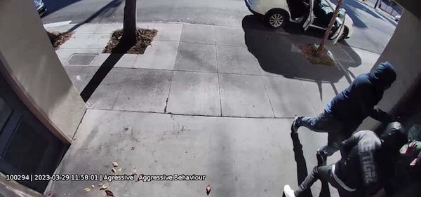
A rule which fires when fight behaviour is detected in the field of view for longer than the specified duration.
Note: Fight does not require a zone and runs independently of the tracker. Enabling this algorithm, by adding this rule, will impact channel capacity,SER as the algorithm runs in addition to the channels selected tracker.
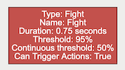
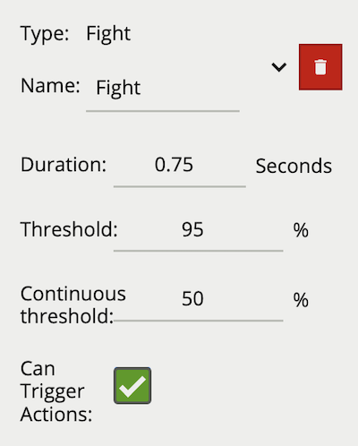
| Property | Description | Default Value |
|---|---|---|
| Name | A user-specified name for this rule | “Fight #” |
| Can Trigger Actions | Specifies whether events generated by this rule trigger actions | Active |
| Duration | Period of time before a fight triggers the rule | 0.75 |
| Threshold | Confidence threshold before a fight is detected | 95 |
| Continuous Threshold | Minimum persistent confidence threshold required for duration | 50 |
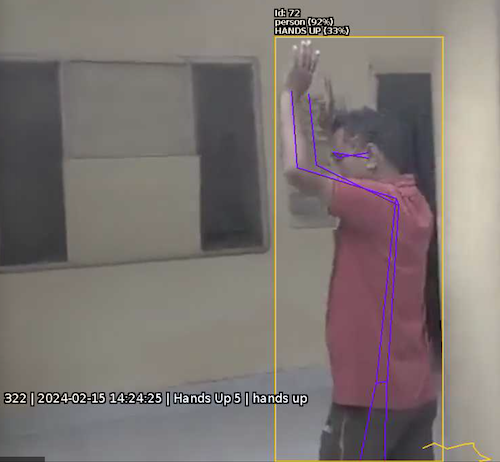
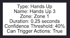
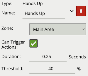
The Hands Up rule detects when a object classified as a Person, by the Deep Learning Skeleton Tracker, has their hands up.
When the Hands Up rule is added to a channel configuration, the Hands Up detection algorithm begins to run in the background on any detected person. Classification of Hands Up is based on the skeleton key point metadata generated by the Deep Learning Skeleton Tracker. Currently this rule is only available when using the Deep Learning Skeleton Tracker.
| Property | Description | Default Value |
|---|---|---|
| Name | A user-specified name for this rule | “Hands Up #” |
| Zone | The zone this rule is associated with | None |
| Duration | Period of time a person must have their hands up before the rule triggers | 0.25 seconds |
| Confidence Threshold | The algorithm confidence (as a percentage) required to trigger the rule | 40 |
| Can Trigger Actions | Specifies whether events generated by this rule trigger actions | Active |
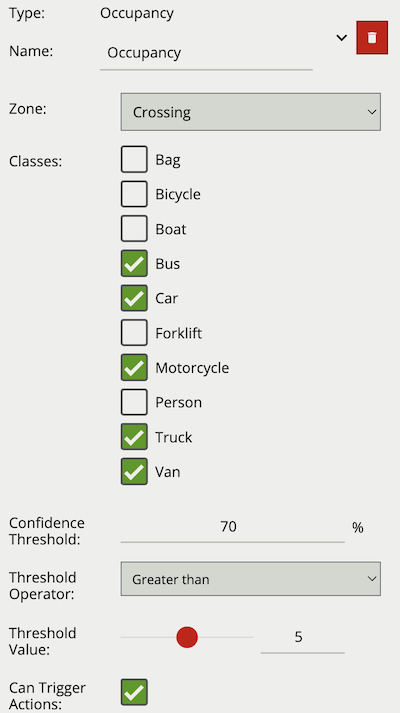
The Occupancy rule counts the number of objects, with a specified class, that are present in the defined zone. The Occupancy rule will generate an event every time this count changes.
The Threshold Operator allows the user to limit when the Occupancy rule generates an event. Based on the selected behaviour and a defined Threshold Value, the Occupancy rule can be configured to only send events in specific scenarios. Threshold Operators include:
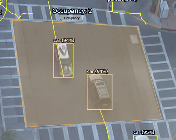
When added, a counter object is visualised on the video stream as seen below. The counter is repositioned using the ‘handle’ beneath the rule name and moving the counter to the desired location.
Right-clicking the mouse (or tap-and-hold on a tablet) on the grid displays the context menu:
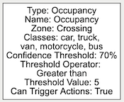
| Property | Description | Default Value |
|---|---|---|
| Name | A user-specified name for this rule | “Occupancy #” |
| Zone | The zone this rule is associated with | None |
| Classes | The object classes allowed to trigger an alert | None |
| Confidence Threshold | The algorithm confidence (as a percentage) required to trigger the rule | 70 |
| Threshold Operator | Defines when a Counter will trigger events based on the threshold | None |
| Threshold Value | The value used by the Threshold Operator to define the behaviour | 0 |
| Can Trigger Actions | Specifies whether events generated by this rule trigger actions | Active |
A rule which fires an event when an object is first detected in a particular zone.
Note: The Presence rule encapsulates a variety of different behaviour, for example the Presence rule will trigger in the same circumstances as an Enter and Appear rule. The choice of which rule is most appropriate will be dependant on the scenario.
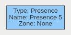
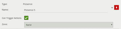
| Property | Description | Default Value |
|---|---|---|
| Name | A user-specified name for this rule | “Presence #” |
| Can Trigger Actions | Specifies whether events generated by this rule trigger actions | Active |
| Zone | The zone this rule is associated with | None |
The stopped rule detects objects which are stationary inside a zone for longer than the specified amount of time. The stopped rule requires a zone to be selected before being able to configure an amount of time.
Note: The stopped rule does not detect abandoned objects. It only detects objects which have moved at some point and then become stationary.
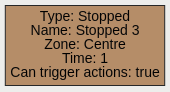
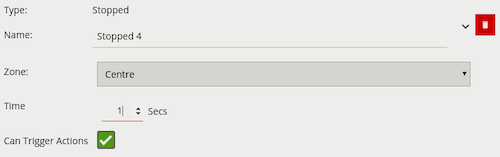
| Property | Description | Default Value |
|---|---|---|
| Name | A user-specified name for this rule | “Stopped #” |
| Zone | The zone this rule is associated with | None |
| Interval | Period of time before a stopped object triggers the rule | 0.5 seconds |
| Can Trigger Actions | Specifies whether events generated by this rule trigger actions | Active |
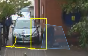
The abandoned and removed object rule triggers when an object has been either left within a defined zone. E.g. a person leaving a bag on a train platform, or when an object is removed from a defined zone. The abandoned rule has a duration property which defines the amount of time an object must have been abandoned for, or removed for, to trigger the rule.
Below is a sample scenario where a bag is left in a defined zone resulting in the rule triggering.
![]()
Below is a similar example scenario where the bag is removed from the defined zone resulting in the rule triggering.
![]()
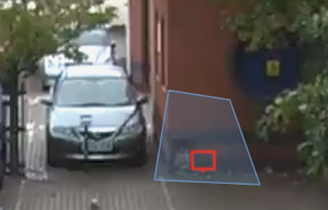
Note: The algorithm used for abandoned and removed object detection is the same in each case, and therefore cannot differentiate between objects which have been abandoned or removed. This is because the algorithm only analyses how blocks of pixels change over time with respect to a background model. Note: The algorithm used for abandoned and removed object will only work when the Object Tracker is selected under Trackers
| Property | Description | Default Value |
|---|---|---|
| Name | A user-specified name for this rule | “Abandoned #” |
| Zone | The zone this rule is associated with | None |
| Duration | Period of time a object must have been abandoned or removed before the rule triggers | 0 |
| Can Trigger Actions | Specifies whether events generated by this rule trigger actions | Active |
The tailgating rule detects objects which cross through a zone or over a line within quick succession of each other.
In this example, object 1 is about to cross a detection line. Another object (object 2) is following closely behind. The tailgating detection threshold is set to 5 seconds. That is, any object crossing the line within 5 seconds of an object having already crossed the line will trigger the object tailgating rule.
Object 2 crosses the line within 5 seconds of object 1. This triggers the tailgating filter and raises an event.
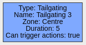
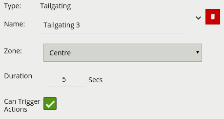
| Property | Description | Default Value |
|---|---|---|
| Name | A user-specified name for this rule | “Tailgating #” |
| Zone | The zone this rule is associated with | None |
| Duration | Maximum time between first and second object entering a zone to trigger the rule | 1 second |
| Can Trigger Actions | Specifies whether events generated by this rule trigger actions | Active |
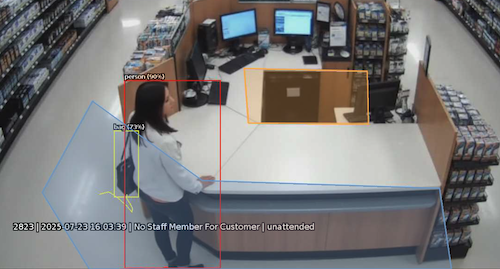
The unattended rule triggers when an object, with a specified class, is present in the customer zone, while no object with the specified class is in the attendant zone for a set duration.
In this example, a person has been present in the Customer zone for 5 seconds, while no person has been in the Attendant zone for that duration, resulting in the rule triggering.
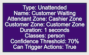
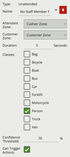
| Property | Description | Default Value |
|---|---|---|
| Name | A user-specified name for this rule | “Unattended #” |
| Attendant Zone | The zone which must not have an object with the set class present for the duration | None |
| Customer Zone | The zone which must have an object with the set class present for the duration | None |
| Duration | Maximum time between first and second object entering a zone to trigger the rule | 1 second |
| Classes | The object classes allowed to trigger an alert | None |
| Confidence Threshold | The algorithm confidence required to trigger the filter | 10 |
| Can Trigger Actions | Specifies whether events generated by this rule trigger actions | Active |
Below is a list of the currently supported filters, along with a detailed description of each.
When filters are used to trigger an action the rule type property is propagated from the filter input. For example, if the input to the speed filter is a presence rule, then actions generated as a result of the speed filter will have a presence event type.
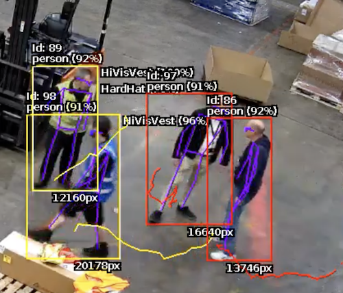
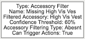
The accessory filter provides a way to check if a given person, which has triggered an input, is wearing, or not wearing, a particular accessory.
Due to the use cases associated with accessory detection, Accessory Filtering Type is required to differentiate between a person with the detected accessory (Present), a person classified as not wearing the accessory (Not Present) and someone not yet evaluated. In the latter case Accessory Filter will not generate a rule as a decision has not yet been made.
Classification of Accessory is based on the skeleton key point metadata generated by the Deep Learning Skeleton Tracker. Currently this rule is only available when using the Deep Learning Skeleton Tracker.
Commonly, this rule is combined with a presence rule, an example rule graph is provided to illustrate this below. The following image illustrates how such a rule combination triggers on people not detected wearing a high-visibility vest, but those wearing a high visibility vest do not trigger the rule.
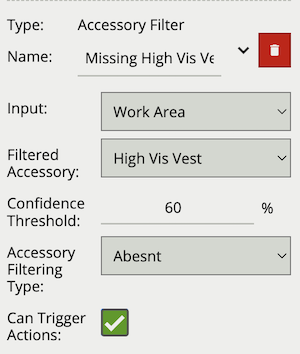
| Property | Description | Default Value |
|---|---|---|
| Name | A user-specified name for this rule | “Accessory #” |
| Can Trigger Actions | Specifies whether events generated by this rule trigger actions | Active |
| Input | The input rule | None |
| Filtered Accessory | The type of accessory the rule will check for | High Vis Vest |
| Confidence Threshold | The algorithm confidence required to trigger the filter | 60 |
| Acc. Filtering Type | Specifies if the rule should trigger if accessory is present or not | Present |
The logical rule example below checks if an object triggering the presence rule Presence Rule, attached to zone Work Area, is not detected as wearing a Hi-Vis Vest.
Only the Accessory Filter is set to Can Trigger Actions, meaning only this component of the logical rule will be available as a source for actions. In this example, any action generated by the accessory filter will have the event type Presence.

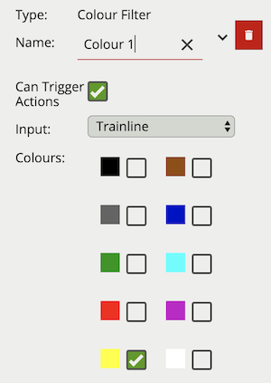
The colour filter rule utilises the Colour Signature algorithm, providing the ability to filter out objects based on an object’s colour components.
The Colour Signature algorithm groups the pixel colours of an object. When a Colour Filter rule is added to a channel, any object that is tracked by VCAserver will also have its pixels grouped into 10 colours. By default this information is added to VCAserver’s metadata, available as tokens, via the SSE metadata service or that channel’s RTSP metadata stream.
The colour filter allows you to select one or more of these colour bins, and will trigger only if the subject object contains one or more of those selected colours.
The below image shows an example tracked object with the colour signature annotations enabled. Here the top four colours which make up more than 5% of the object are represented by the colour swatch attached to the object. In this case a person being tracked in the scene with high visibility safety clothing. Here the colour filter is set to trigger on Yellow, detecting the person but ignoring the shadow.
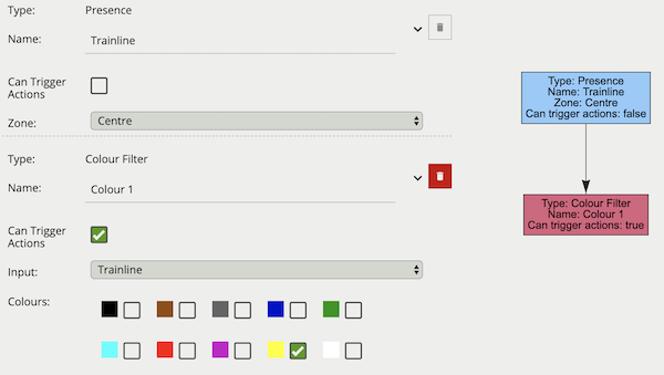
Typically, the colour filter would be combined with another rule(s) to prevent unwanted objects from triggering an alert, an example rule graph is provided to illustrate this below.
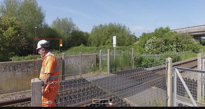
The previous image illustrates how the colour filter prevents objects, which do not contain the specified colours, from generating an event. In this case only the person generates an event but not the train line.
Note: the channel must have the Colour Signature enabled for the colour filter to work.
| Property | Description | Default Value |
|---|---|---|
| Name | A user-specified name for this rule | “Colour Filter #” |
| Can Trigger Actions | Specifies whether events generated by this rule trigger actions | Active |
| Input | The input rule | None |
| Colours | The colours allowed to trigger an alert | All Unchecked |
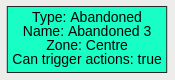
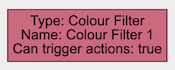
The logical rule example below checks if the object triggering the presence rule Train line attached to zone Centre, also contains the colour Yellow as one of the top four colours by percentage.
Only the Colour filter is set to Can Trigger Actions, meaning only this component of the logical rule will be available as a source for actions.
The object filter provides the ability to filter out objects which trigger a rule, if they are not classified as a certain class (e.g. person, vehicle). The available classes which can be used to filter, depend on which tracker is currently selected. In cases where the class is assigned via a deep learning model (DLOT, DLPT), the confidence threshold can also be used to further filter out objects which the model is not confident about its class. If a channel running the Object Tracker is both calibrated and has the Deep Learning Classifier enabled, the Object Filter will default to the Deep Learning Classifier classification options.
The object classification filter must be combined with another rule(s) to prevent unwanted objects from triggering an alert, an example rule graph is provided to illustrate this below.
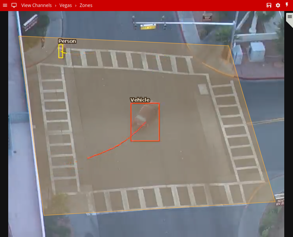
The previous image illustrates how the object classification filter configured with Vehicle class, only triggers on Vehicle objects. The person in the zone is filtered out since the Person class is not selected in the filter list.
Note: when using the Object Tracker, the channel must be calibrated for the object classification filter to be available.
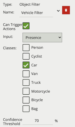
| Property | Description | Default Value |
|---|---|---|
| Name | A user-specified name for this rule | “Object Filter #” |
| Can Trigger Actions | Specifies whether events generated by this rule trigger actions | Active |
| Input | The input rule | None |
| Classes | The object classes allowed to trigger an alert | None |
| Confidence Threshold | The algorithm confidence required to trigger the filter | 10 |
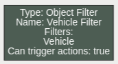
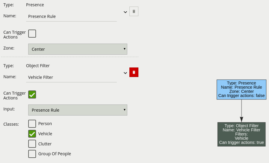
The logical rule example below checks if the object triggering the presence rule Presence Rule attached to zone Centre, is also classified as a Vehicle as specified by the Object Filter Vehicle Filter.
Only the Object filter is set to Can Trigger Actions, meaning only this component of the logical rule will be available as a source for actions. In this example, any action generated by the speed filter will have the event type Presence.
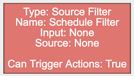
The other source filter provides the ability to use Other Sources to filter an input rule in a rule graph. The other source filter will only trigger an event in cases when the selected other source evaluates as on, whilst the input rule triggers an event.
Valid Other Sources and the valid on scenario are outlined in the table below:
| Other Source Type | on Condition |
off Condition |
|---|---|---|
| HTTP | The observable state is set true |
The observable state is set false |
| Schedule | The current system clock falls into a scheduled ‘on’ period | The current system clock falls into a scheduled ‘off’ period |
Typically the other source filter would be used to limit a rule(s) from firing if an external requirement is not met. For example, using a Schedule source with the source filter only triggers events if the input rule fires during set periods of time. Alternatively, using a HTTP source would only trigger an event when the input rule triggers and the HTTP source state is set to true. An example rule graph is provided to illustrate this below.
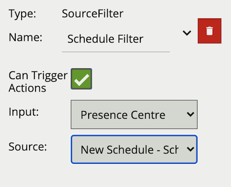
| Property | Description | Default Value |
|---|---|---|
| Name | A user-specified name for this rule | “Other Source #” |
| Can Trigger Actions | Specifies whether events generated by this rule trigger actions | Active |
| Input | The input rule | None |
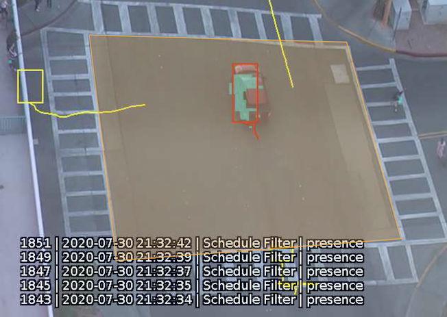
| Source | The other source | None |
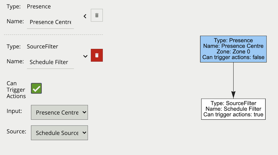
The logical rule example below will only generate an event if the current system time falls within an on period, defined in the source Schedule Source and the input rule Presence Centre attached to zone Zone 0, triggers an event.
Only the other source filter is set to Can Trigger Actions, meaning only this component of the logical rule will be available as a source for actions. In this example, any action generated by the other source filter will have the event type Presence.
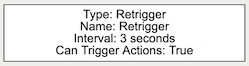
The Retrigger Filter acts as an event pass through, which only generates an event if the input has not fired previously within the defined interval.
Typically, the Retrigger Filter would be applied at the end of a rule(s) combination to prevent duplicate alarms being sent, this provides more granular control than the Event Retrigger Time option. Events produced by the Retrigger Filter will have the event type of the input rule.
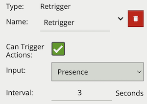
| Property | Description | Default Value |
|---|---|---|
| Name | A user-specified name for this rule | “Retrigger #” |
| Can Trigger Actions | Specifies whether events generated by this rule trigger actions | Active |
| Input | The input rule | None |
| Interval | Period in which the input event cannot generate another event | 3 |
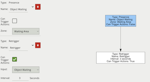
The logical rule example below takes as input the presence rule Object Waiting attached to zone Waiting Area, and will generate an event a maximum of once every 3 seconds, assuming the presence rule had objects regularly triggering it.
Only the Retrigger filter is set to Can Trigger Actions, meaning only this component of the logical rule will be available as a source for actions. This will then limit any associated actions from generating messages more than once every three seconds. Additionally in this case, the event generated by the Retrigger filter will have the event type Presence.
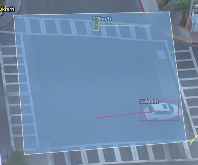
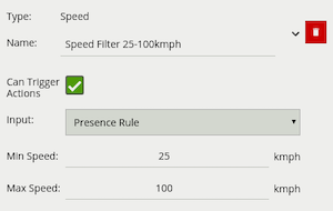
The speed filter provides a way to check if the speed of an object, which has triggered an input, is moving within the range of speeds defined by a lower and upper boundary.
Note: The channel must be calibrated in order for the speed filter to be available.
Commonly, this rule is combined with a presence rule, an example rule graph is provided to illustrate this below. The following image illustrates how such a rule combination triggers on the car moving at 52 km/h, but the person moving at 12 km/h falls outside the configured range (25-100 km/h) and thus does not trigger the rule.
| Property | Description | Default Value |
|---|---|---|
| Name | A user-specified name for this rule | “Speed #” |
| Can Trigger Actions | Specifies whether events generated by this rule trigger actions | Active |
| Input | The input rule | None |
| Min Speed | The minimum speed (km/h) an object must be going to trigger the rule | 0 |
| Max Speed | The maximum speed (km/h) an object can be going to trigger the rule | 0 |
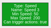
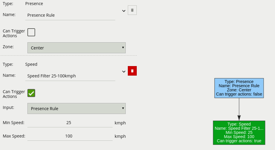
The logical rule example below checks if an object triggering the presence rule Presence Rule attached to zone Centre, is also travelling between 25 and 100 km/h as specified by the speed rule Speed Filter 25-100 km/h.
Only the Speed Filter is set to Can Trigger Actions, meaning only this component of the logical rule will be available as a source for actions. In this example, any action generated by the speed filter will have the event type Presence.
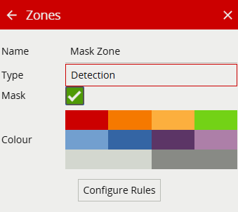
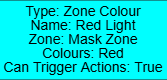
The Zone Colour filter allows the detected colours within a zone, with mask enabled, to trigger an event.
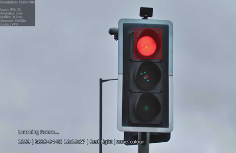
Note: For the zone colour filter to function correctly, please ensure that a mask zone is enabled in the zone menu.
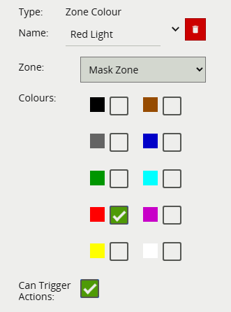
| Property | Description | Default Value |
|---|---|---|
| Name | A user-specified name for this rule | “Zone Colour Filter #” |
| Can Trigger Actions | Specifies whether events generated by this rule trigger actions | Active |
| Zone | The input zone | None |
| Colours | The colours allowed to trigger an alert | All Unchecked |
The logical rule example below checks when a traffic light signal turns red.
Below is a list of the currently supported conditional rules, along with a detailed description of each.
A logical operator that combines two rules and only fires events if both inputs are true.
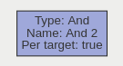
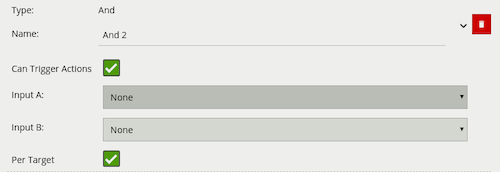
| Property | Description | Default Value |
|---|---|---|
| Name | A user-specified name for this rule | “And #” |
| Can Trigger Actions | Specifies whether events generated by this rule trigger actions | Active |
| Input A | The first input | None |
| Input B | The second input | None |
| Per Target | Fire one event per tracked object | Active |
If we consider a scene with two presence rules, connected to two separate zones, connected by an AND rule, the table below explains the behaviour of the Per Target property. Note that object here refers to a tracked object, as detected by the VCA tracking engine.
| State | Per Target | Outcome |
|---|---|---|
| Object A in Input A, Object B in input B | On | Two events generated, one for each object |
| Object A in Input A, Object B in input B | Off | Only one event generated |
Additionally, it is important to note that if the rule fires when Per Target is switched off, it will not fire again until it is ‘reset’, i.e. until the AND condition is no longer true.
A logical operator that fires events when its input has occurred continuously for a user-specified time.
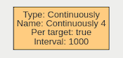
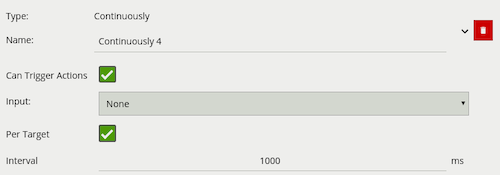
| Property | Description | Default Value |
|---|---|---|
| Name | A user-specified name for this rule | “Continuously #” |
| Can Trigger Actions | Specifies whether events generated by this rule trigger actions | Active |
| Input | The input rule | None |
| Per Target | Fire one event per tracked object. See description below for more details | Active |
| Interval | The time in milliseconds | 1 |
Considering a scene with a Presence rule associated with a zone and a Continuously rule attached to that Presence rule, when the Per Target property is on, the rule will generate an event for each tracked object that is continuously present in the zone. When it is off, only one event will be generated by the rule, even if there are multiple tracked objects within the zone. Additionally, when Per Target is off, the rule will only generate events when there is change of state, i.e. the rule condition changes from true to false or vice versa. When Per Target is off, the state will change when:
Any number of objects enter the zone in question and remain in the zone
All objects leave the zone in question
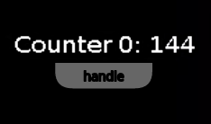
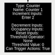
Counters can be configured to count the number of times a rule is triggered. For example, the number of people crossing a line. The counter rule is designed to be utilised in two ways:
Increment / Decrement: whereby a counter is incremented by the attached rule(s) (+1 for each rule trigger), and decremented by another attached rule(s) (-1 for each rule trigger).
Occupancy: whereby the counter reflects the number of objects that are currently triggering the attached rule(s).
More than one rule can be assigned to any of a counter’s three inputs. This allows, for example, the occupancy of two presence rules to be reflected in a single counter, or more than one entrance / exit gate to reflect in a single counter. An example rule graph is provided to illustrate this below.
Broadly speaking a single counter should not be used for both purposes occupancy and increment / decrement.
The Counter’s Threshold Operator allows the user to limit when a counter generates an event. Based on the selected behaviour and a defined Threshold Value, the counter can be configured to only send events in specific scenarios. Threshold Operators include:
The Counter’s Reset allows another Rule or selected Other Source(s) to reset the counter to 0. An example use case could be to zero out counters at the end of the day. Any Basic Input, Filter or Conditional rule can be used to trigger the Counter’s reset. The HTTP and Schedule Other Source(s) can be used to trigger the Counter’s reset.
When added, a counter object is visualised on the video stream as seen below. The counter is repositioned using the ‘handle’ beneath the rule name and moving the counter to the desired location.
Right-clicking the mouse (or tap-and-hold on a tablet) on the grid displays the context menu:
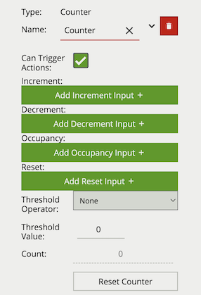
| Property | Description | Default Value |
|---|---|---|
| Name | A user-specified name for this rule | “Counter #” |
| Increment | The rule which, when triggered, will add one to the counter | None |
| Decrement | The rule which, when triggered, will subtract one from the counter | None |
| Occupancy | Sets counter to current number of the rule’s active triggers | None |
| Reset | Resets the count to 0 when the assigned rule or other source triggers |
None |
| Threshold Operator | Defines when a Counter will trigger events based on the threshold | None |
| Threshold Value | The value used by the Threshold Operator to define the behaviour | 0 |
| Can Trigger Actions | Specifies whether events generated by this rule trigger actions | Active |
| Reset Counter | A button allowing the counter value to be reset to 0 | None |
* E.g. if a Presence rule is set as the occupancy target and two objects are currently triggering that Presence rule, the counter will show the value of 2.
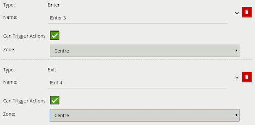
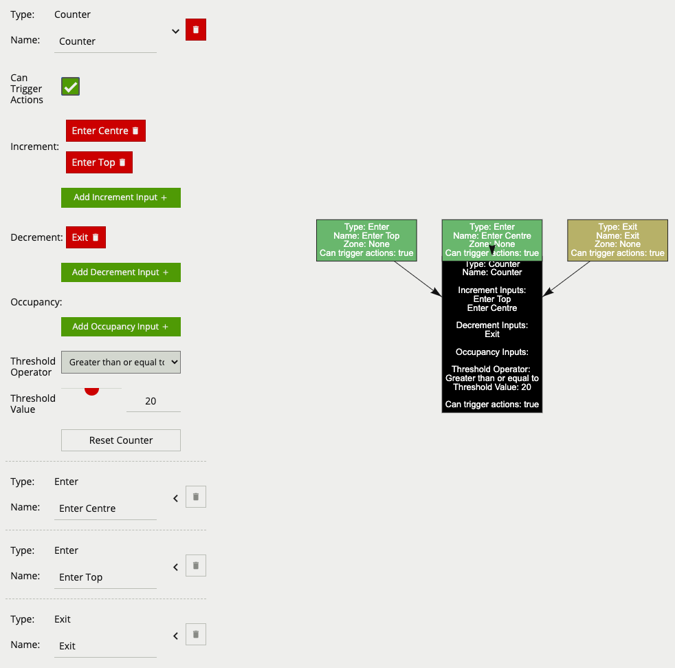
The below counter example increments a counter based on two enter rules, Enter Centre and Enter Top attached to the zones Centre and Top respectively, this means that when either of these enter rules triggers the counter will be incremented by + 1. The counter also decrements based on the exit rule Exit, which will subtract 1 from the counter each time an object exits the zone Centre. The Threshold Operator and Threshold Value, limit the counter to only generate events when the count is more than 20.
Only the counter rule Counter is set to Can Trigger Actions, meaning only this component of the logical rule will be available as a source for actions. In this case an action using this rule as a source will trigger every time the counter changes.
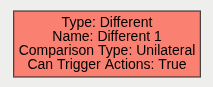
A logical operator that combines two rules and only fires events if the targets inside the events are different.

| Property | Description | Default Value |
|---|---|---|
| Name | A user-specified name for this rule | “Different #” |
| Can Trigger Actions | Specifies whether events generated by this rule trigger actions | Active |
| Input A | The first input | None |
| Input B | The second input | None |
| Comparison Type | How to compare targets between the 2 events | Unilateral |
If we consider a scene with two presence rules, connected to two separate zones, connected by an DIFFERENT rule, the table below explains the behaviour of the Comparison Type property. Note that object here refers to a tracked object, as detected by the VCA tracking engine.
| State | Comparison Type | Outcome |
|---|---|---|
| Object A in Input A, Object A & B in input B | Unilateral | No event is generated |
| Object A in Input A, Object A & B in input B | Bilateral | Only one event generated, containing Object B |
| Object A & B in Input A, Object A in input B | Unilateral | Only one event generated, containing Object B |
| Object A & B in Input A, Object A in input B | Bilateral | Only one event generated, containing Object B |
A logical operator that generates an event when the input rule becomes false.
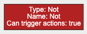
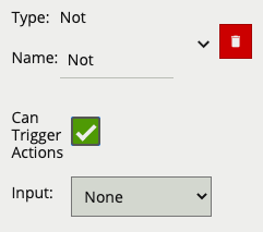
| Property | Description | Default Value |
|---|---|---|
| Name | A user-specified name for this rule | “Not #” |
| Can Trigger Actions | Specifies whether events generated by this rule trigger actions | Active |
| Input | The input rule | None |
| Per Target | Fire one event per tracked object | Active |
A logical operator that combines two rules and fires events if either input is true.
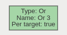
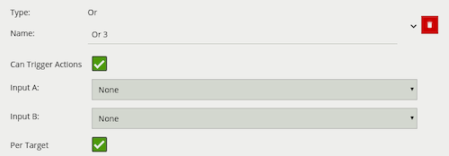
| Property | Description | Default Value |
|---|---|---|
| Name | A user-specified name for this rule | “Or #” |
| Can Trigger Actions | Specifies whether events generated by this rule trigger actions | Active |
| Input A | The first input | None |
| Input B | The second input | None |
| Per Target | Fire one event per tracked object | Active |
If we consider a scene with two Presence rules connected to two separate zones, connected by an OR rule, the table below explains the behaviour of the Per Target property.
| State | Per Target | Outcome |
|---|---|---|
| Object A in Input A, No object in input B | On | Two events generated, one for each object |
| No object in Input A, Object B in input B | On | Only one event generated (for Object B) |
| Object A in Input A, No object in input B | On | Only one event generated (for Object A) |
| Object A in Input A, No object in input B | Off | Only one event generated |
| No object in Input A, Object B in input B | Off | Only one event generated |
| Object A in Input A, No object in input B | Off | Only one event generated |
Additionally, it is important to note that if the rule fires when Per Target is switched off, it will not fire again until it is ‘reset’, i.e. until the OR condition is no longer true.
A logical operator that triggers for input events which were active at some point in a past window of time. This window is defined as between the current time and the period before the current time (specified by the Interval value).
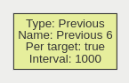
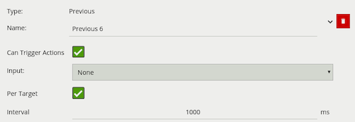
| Property | Description | Default Value |
|---|---|---|
| Name | A user-specified name for this rule | “Previous #” |
| Can Trigger Actions | Specifies whether events generated by this rule trigger actions | Active |
| Input | The input rule | None |
| Per Target | Fire one event per tracked object | Active |
| Interval | The time in milliseconds | 1 |
A logical operator that triggers when an input rule is triggered a set number of times within a defined period. The Duration period is a window of time computed from every input event. For example, with a Repeatedly rule configured to generate an event when the input triggers three times in eight seconds, and that input rule triggers four times in eight seconds, the repeatedly rule will trigger after both the third input rule trigger and again after the fourth. This is because the first three triggers (events 1-3) fired within an 8 second window, additionally the second set (events 2-4) also occurred within their own 8 second window.
The Per Target option specifies that it must be the same tracked object that triggers the input.
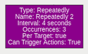
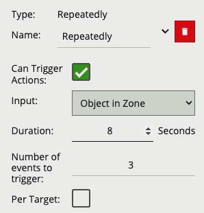
| Property | Description | Default Value |
|---|---|---|
| Name | A user-specified name for this rule | “Repeatedly #” |
| Can Trigger Actions | Specifies whether events generated by this rule trigger actions | Active |
| Input | The input rule | None |
| Duration | The time in which the Number of Events to Trigger must fire |
3 |
| Number of Events to Trigger | The number of times the input is required to trigger | 4 |
| Per Target | Specifies if the input needs to be triggered by the same object | Inactive |
The ‘double-knock’ logical rule triggers when an object enters a zone which had previously entered another defined, zone within a set period of time. The interval on the Previous rule decides how much time can elapse between the object entering the first and second zone. The graph for a double-knock logical rule is as follows:
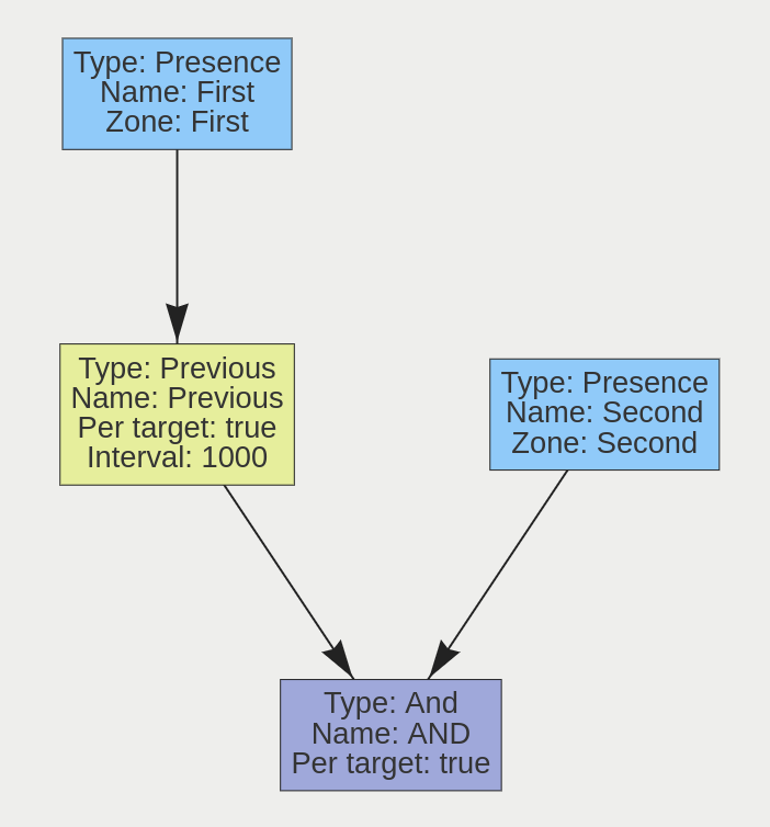
The rule may be interpreted as follows: ‘An object is in Zone 2, and was previously in Zone 1 in the last 1000 milliseconds’. This rule can be used as a robust way to detect entry into an area. Since the object has to enter two zones in a specific order, it has the ability to eliminate false positives that may arise from a simple Presence rule.
This rule triggers when an object is present in either Zone A or Zone B. Its graph is as follows:
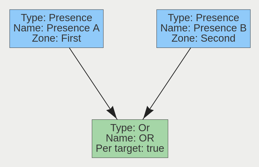
A typical use case for this rule is having multiple areas where access is prohibited, but the areas cannot be easily covered by a single zone. Two zones can be created, associated with two separate Presence rules, and they can then be combined using an Or rule.
Actions are user configured outputs which can be triggered by a variety of events that occur within VCAserver.
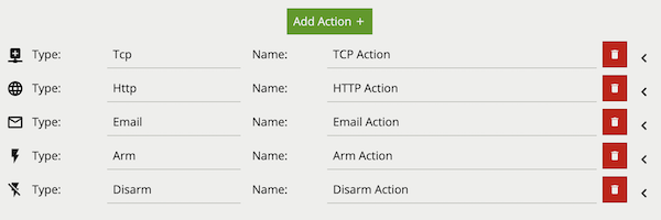
Common Properties:
Any action can have multiple event sources assigned to it. Once an event source is assigned to an action, any event generated by that source will trigger the action. Available event sources are grouped according to Video Sources including either, customer defined logical rules (with the Can Trigger Action box checked), loss of signal events and any configured Digital Input, Armed, Disarmed or Interval sources.
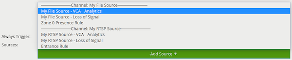
The TCP action sends data to a remote TCP server when triggered. The format of the body is configurable with a mixture of plain text and Tokens, which are substituted with event-specific values at the time an event is generated.
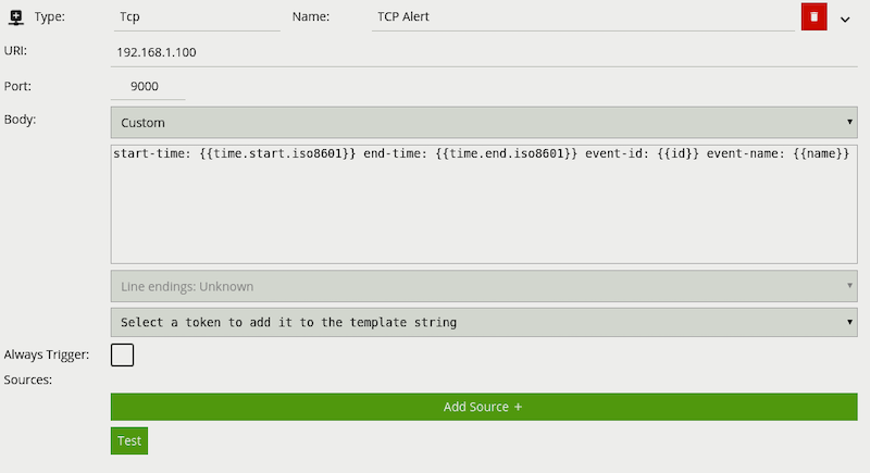
URI: The IP address or hostname of the remote TCP server where the event data should be transmitted.
Port: The port on which the remote TCP server is listening for incoming TCP connections.
Body: The body of the TCP message to transmit. Can be a mixture of plain text and any supported Tokens, which will be replaced with event-specific data at the time an event is generated. The TCP Body supports escape characters, allowing for inputs such NULL terminated strings (\x00). In turn these escape characters can be escaped through the use of an additional \ e.g. (\\x00).
See the Tokens topic for full details about the token system and example templates.
The email action sends events in pre- or user-configured formats to remote email servers.
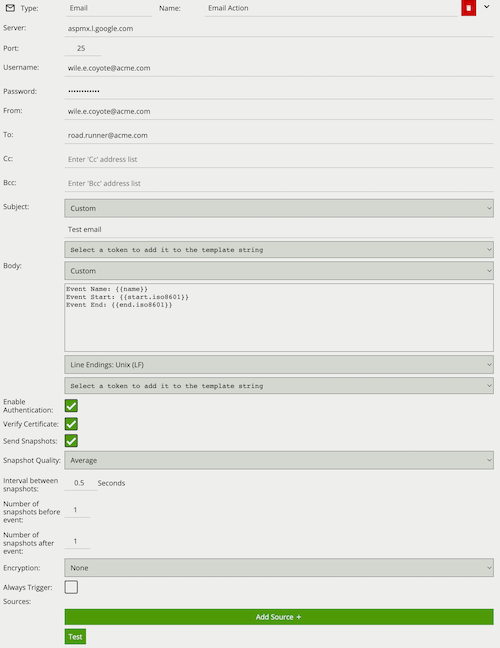
Server: SMTP server address.
Port: SMTP server port.
Username: The username of the email account used to send emails on the SMTP server.
Password: The password of the email account used to send emails on the SMTP server.
From: The email address of the sender.
To: The email address of the recipient.
Cc: Email address/addresses of any carbon-copy recipients.
Bcc: Email address/addresses of any blind carbon-copy recipients.
Subject: The tokenised template of the email subject.
Body: Tokenised template of the email body.
Enable Authentication: Check to enable SMTP authentication.
Verify Certificate: Check to verify the remote SSL certificate.
Send Snapshots: Check to attach annotated snapshots to the email.
Snapshot Quality: Select the quality of the snapshots attached to the email.
Interval between snapshots: Set the snapshot capture rate in 250 milliseconds (ms) increments.
Number of Snapshots sent before event: Set the number of pre-event snapshots to attach to the email.
Number of Snapshots sent after event: Set the number of post-event snapshots to attach to the email.
Encryption: The type of encryption used for SMTP communication. Valid options are None, TLS, TLSv1.0, TLSv1.1, TLSv1.2 and TLSv1.3.
See the Tokens topic for full details about the token system and example templates.
It is not advised to enable Send Snapshots on an action linked to a loss of signal event source. If the signal has been lost, snapshots will not be gathered until the signal is restored, delaying the action.
The HTTP action sends a text/plain HTTP or HTTPs request to a remote endpoint when triggered. The URL, HTTP headers and message body are all configurable with a mixture of plain text and Tokens, which are substituted with event-specific values at the time an event is generated. Additionally, snapshots from the camera can be sent as a multipart/form-data request with the configured snapshots included as image/jpeg’s. HTTP actions are sent using the HTTP/1.1 standard.
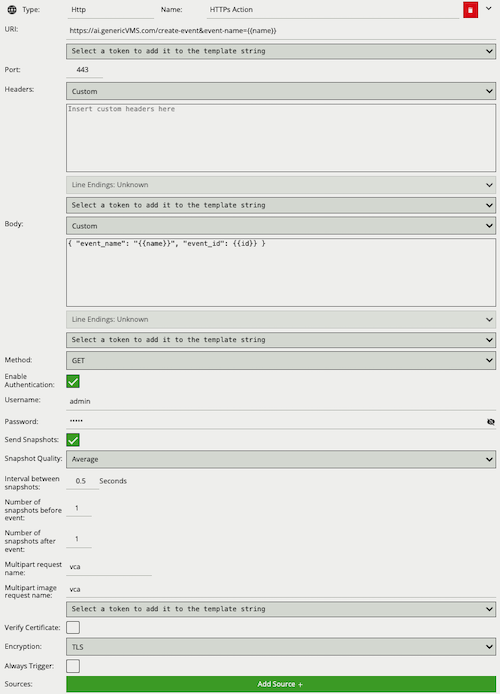
URI: The remote URI to request when executing the HTTP action. As illustrated in the figure, the URI can contain Tokens, which will be replaced with event-specific data at the time an event is generated. If specifying user credentials in plain text is undesirable, they can be specified in the Header section encoded as a base 64 string as part of a standard HTTP Authorization header.
Port: The remote server port.
Headers: Specifies any HTTP headers to send in the HTTP request. Examples may include Authorization or Content-Type headers. Any necessary headers will normally be specified by the remote server API. Each header should be placed on a new line. When the headers are transmitted a CRLF (\r\n) is automatically inserted between each header, and between the last header and the message body. Example:
Content-Type: application/json
Authorization: Basic <API_TOKEN_EXAMPLE>
Body: Specifies the body of the HTTP request. Can be a mixture of plain text and any supported Tokens, which will be replaced with event-specific data at the time an event is generated.
Method: The HTTP request method (verb). Can be one of GET, POST, PUT, DELETE, HEAD. This setting will normally be specified by the remote server API.
Enable Authentication: Check to enable authentication (supports both HTTP Basic and HTTP Digest).
Username: The username to use for authentication.
Password: The password to use for authentication.
Send Snapshots: Check to attach annotated snapshots to the HTTP request.
Snapshot Quality: Select the quality of the snapshots attached to the HTTP request.
Interval between snapshots: Set the snapshot capture rate in 250 milliseconds (ms) increments.
Number of Snapshots sent before event: Set the number of pre-event snapshots to attach to the HTTP request.
Number of Snapshots sent after event: Set the number of post-event snapshots to attach to the HTTP request.
Multipart request name: Sets the text assigned to multipart name. This name will need to be reflected in any scripts that handle this HTTP request, for example in php; this would be by using $_FILES['vca'] where vca is the string set in the multipart field.
Multipart image request name: Sets the text assigned to multipart image name. This name will need to be reflected in any scripts that handle this HTTP request, for example in php; this would be by using $_FILES['vca'] where vca is the string set in the multipart field.
Verify Certificate: Check to verify the certificate of the HTTPs endpoint specified.
Encryption: Select the encryption method used to send the HTTPs request.
See the Tokens topic for full details about the token system and example templates.
It is not advised to enable Send Snapshots on an action linked to a loss of signal event source. If the signal has been lost, snapshots will not be gathered until the signal is restored, delaying the action.
A digital output is a logical representation of a digital output hardware channel. To configure the properties of a physical digital output channel, such as activation time, refer to the Digital IO page.
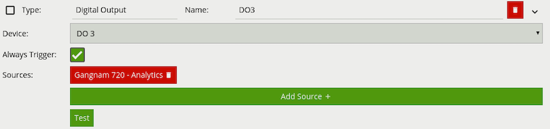
The Arm action sets the device state to armed when triggered.
The Disarm action sets the device state to disarmed when triggered.
The Arm/Disarm functionality provides a means of disabling/enabling all of the configured actions. For example, users may wish to disable all actions when activity is normal and expected (e.g. during normal working hours) and re-enable the actions at times when activity is not expected.
The Arm/Disarm state can be toggled manually by clicking the icon in the Navigation Bar or by using the Arm or Disarm actions.
Camera calibration is required in order for VCAserver to classify objects into different object classes. Once a channel has been calibrated, VCAserver can infer real-world object properties such as speed, height and area and classify objects accordingly.
Camera calibration is split into the following sub-topics:
By default calibration is disabled. To enable calibration on a channel, check the Enable Calibration checkbox.
The calibration page contains a number of elements to assist with calibrating a channel as easily as possible. Each is described below.
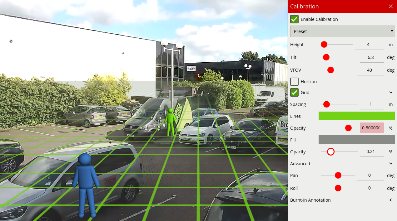
During the calibration process, the features in the video image need to be matched with a 3D graphics overlay. The 3D graphics overlay consists of a green grid that represents the ground plane. Placed on the ground plane are a number of 3D mimics (people-shaped figures) that represent the dimensions of a person with the current calibration parameters. The calibration mimics are used for verifying the size of a person in the scene and are 1.8 metres tall.
The mimics can be moved around the scene to line up with people (or objects which are of a known, comparable height) to a person.
The calibration parameters can be adjusted with the mouse as follows: - Click and drag the ground plane to change the camera tilt angle. - Use the mouse wheel to adjust the camera height. - Drag the slider to change the vertical field of view.
Note: The sliders in the control panel can also be used to adjust the camera tilt angle and height.
The control panel (shown on the right hand side in the image above) contains the following controls:
Right-clicking the mouse (or tap-and-hold on a tablet) on the grid displays the context menu:
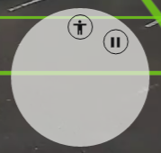
Performing the same action on a mimic displays the mimic context menu:
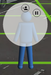
The possible actions from the context menu are:
Calibrating a channel is necessary in order to estimate object parameters such as height, area, speed and classification. If the height, tilt angle and vertical field of view corresponding to the installation are known, these can simply be entered as parameters in the appropriate fields in the control panel.
If however, these parameters are not explicitly known this section provides a step-by-step guide to calibrating a channel.
Find some people, or some people-sized objects in the scene. Try to find a person near the camera, and a person further away from the camera. It is useful to use the play/pause control to pause the video so that the mimics can be accurately placed. Place the mimics on top of or near the people:
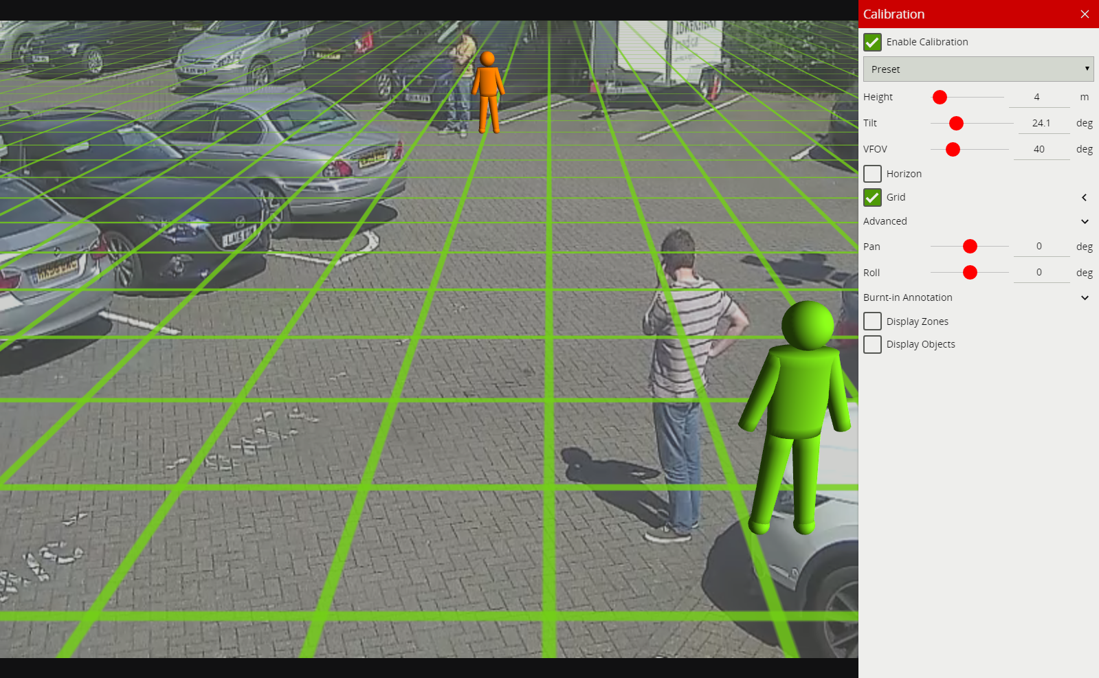
Determining the correct vertical field of view is important for an accurate calibration. The following table shows pre- calculated values for vertical field of view for different sensor sizes.
| Focal Length(mm) | 1 | 2 | 3 | 4 | 5 | 6 | 7 | 8 | |
|---|---|---|---|---|---|---|---|---|---|
| CCD Size (in) | CCD Height(mm) | ||||||||
| 1/6" | 1.73 | 82 | 47 | 32 | 24 | 20 | 16 | 14 | 12 |
| 1/4" | 2.40 | 100 | 62 | 44 | 33 | 27 | 23 | 19 | 17 |
| 1/3.6" | 3.00 | 113 | 74 | 53 | 41 | 33 | 28 | 24 | 21 |
| 1/3.2" | 3.42 | 119 | 81 | 59 | 46 | 38 | 32 | 27 | 24 |
| 1/3" | 3.60 | 122 | 84 | 62 | 48 | 40 | 33 | 29 | 25 |
| 1/2.7" | 3.96 | 126 | 89 | 67 | 53 | 43 | 37 | 32 | 28 |
| 1/2" | 4.80 | 135 | 100 | 77 | 62 | 51 | 44 | 38 | 33 |
| 1/1.8" | 5.32 | 139 | 106 | 83 | 67 | 56 | 48 | 42 | 37 |
| 2/3" | 6.60 | 118 | 95 | 79 | 67 | 58 | 50 | 45 | |
| 1" | 9.60 | 135 | 116 | 100 | 88 | 77 | 69 | 62 | |
| 4/3" | 13.50 | 132 | 119 | 107 | 97 | 88 | 80 |
| Focal Length(mm) | 9 | 10 | 15 | 20 | 30 | 40 | 50 | |
|---|---|---|---|---|---|---|---|---|
| CCD Size (in) | CCD Height(mm) | |||||||
| 1/6" | 1.73 | 11 | 10 | 7 | ||||
| 1/4" | 2.40 | 15 | 14 | 9 | 7 | |||
| 1/3.6" | 3.00 | 19 | 12 | 11 | 9 | 6 | ||
| 1/3.2" | 3.42 | 21 | 16 | 13 | 10 | 7 | ||
| 1/3" | 3.60 | 23 | 20 | 14 | 10 | 7 | 5 | |
| 1/2.7" | 3.96 | 25 | 22 | 15 | 11 | 8 | 6 | |
| 1/2" | 4.80 | 30 | 27 | 18 | 14 | 9 | 7 | 5 |
| 1/1.8" | 5.32 | 33 | 30 | 20 | 15 | 10 | 8 | 6 |
| 2/3" | 6.60 | 40 | 37 | 25 | 19 | 13 | 9 | 8 |
| 1" | 9.60 | 56 | 51 | 35 | 27 | 18 | 14 | 11 |
| 4/3" | 13.50 | 74 | 68 | 48 | 37 | 25 | 19 | 15 |
If the table does not contain the relevant parameters, the vertical FOV can be estimated by viewing the extremes of the image at the top and bottom. Note that without the correct vertical FOV, it may not be possible to get the mimics to match people at different positions in the scene.
If the camera height is known, type it in directly. If the height is not known, estimate it as far as possible and type it in directly.
Adjust the camera tilt angle (and height if necessary) until both mimics are approximately the same size as a real person at that position in the scene. Click and drag the ground plane to change the tilt angle and use the mouse wheel or control panel to adjust the camera height.
The objective is to ensure that mimics placed at various locations on the grid line up with people or people-sized- objects in the scene.
Once the parameters have been adjusted, the object annotation will reflect the changes and classify the objects accordingly.
Once the scene is calibrated, drag or add mimics to different locations in the scene and verify they appear at the same size/height as a real person would. Validate that the height and area reported by the VCAserver annotation looks approximately correct. Note that the burnt-in -annotation settings in the control panel can be used to enable and disable the different types of annotation.
Repeat step 4 until the calibration is acceptable.
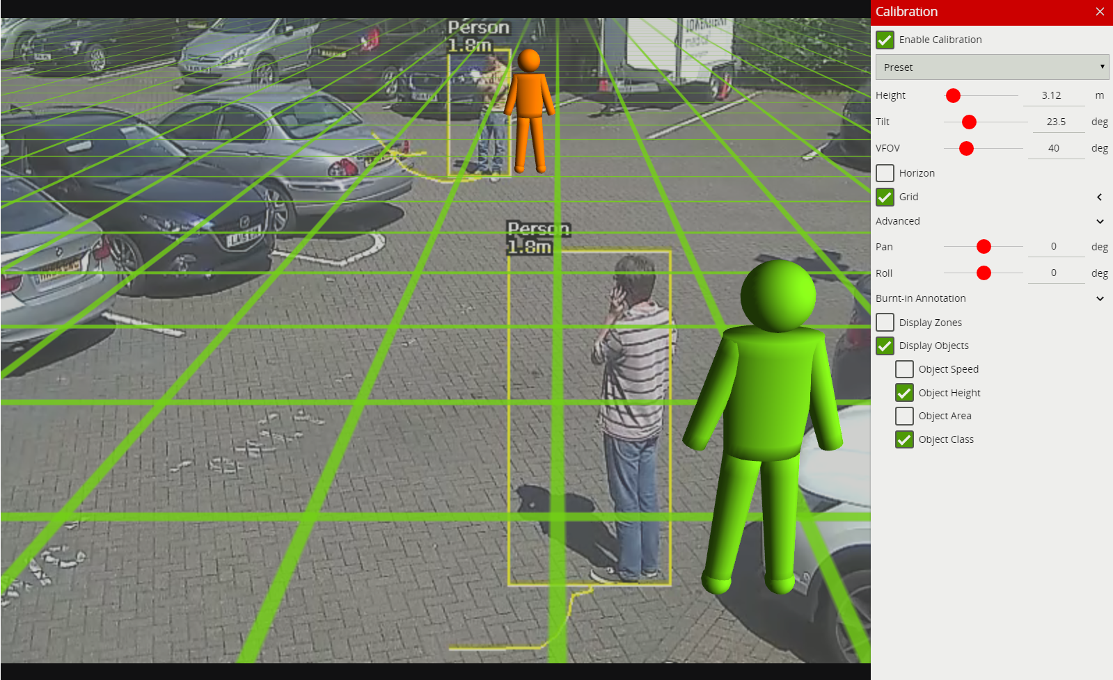
Tip: If it all goes wrong and the mimics disappear or get lost due to an odd configuration, select one of the preset configurations to restore the configuration to normality.
Additional parameters to further improve calibration and enable geographic position metadata.
Pan and Roll settings allow the ground plane to be panned and rolled without affecting the camera calibration parameters. This can be useful to visualize the calibration setup if the scene has pan or roll with respect to the camera.
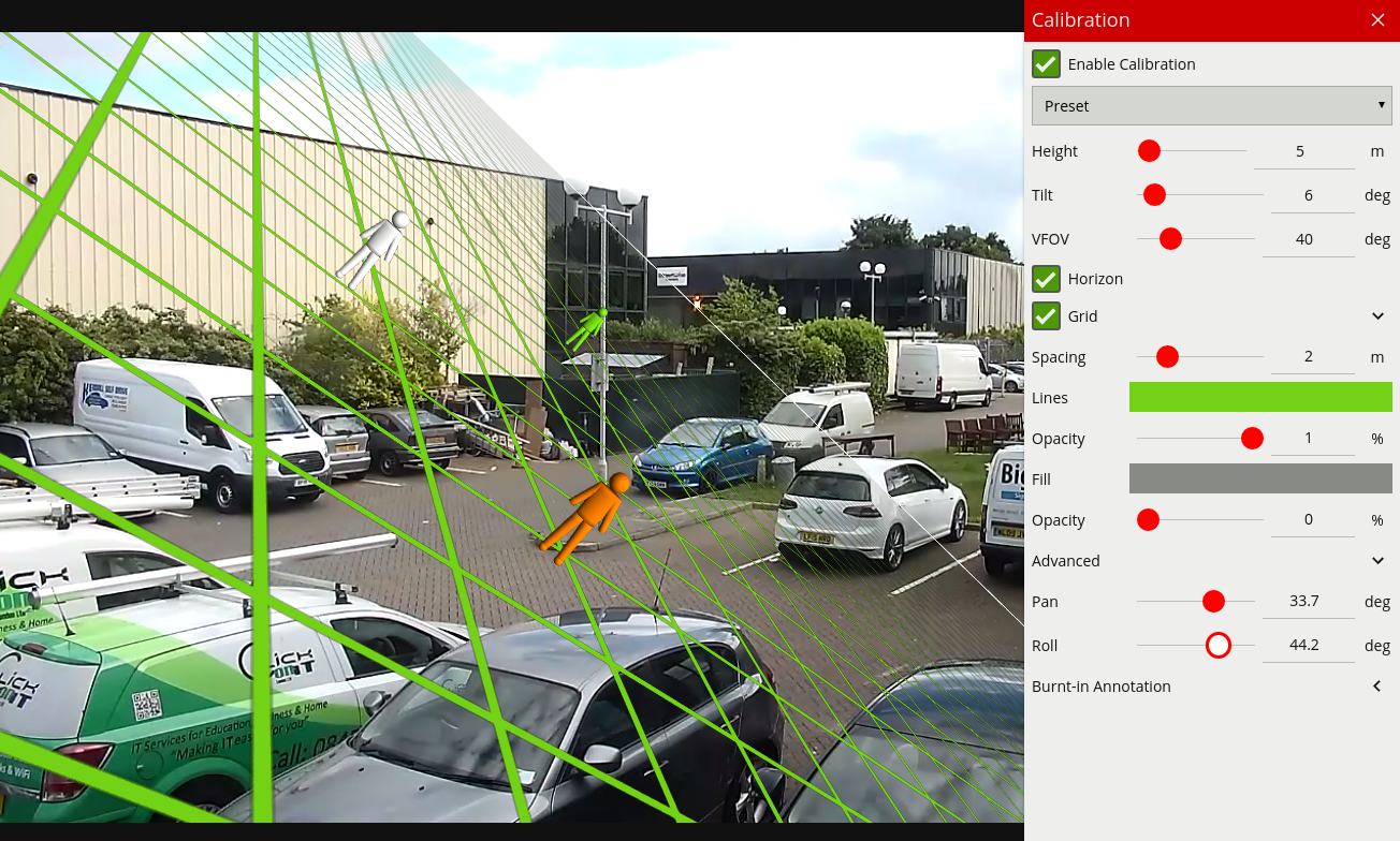
Note: the pan and roll advanced parameters only affect the orientation of the 3D ground plane so that it can be more conveniently aligned with the video scene, and does not actually affect the calibration parameters.
Within the Advanced menu the options are provided to define the camera’s real world position defined as:
These settings, when defined will provide the estimated geographic position for any detected object relative to the camera. This information is available as tokens and within the metadata APIs.
VCAserver can define an object’s class, using either deep learning models or by using properties extracted from an object in a calibrated scene.
Both methods of classification are applied through the use of the Object Filter rule, which evaluates an object against it’s predicted class and filters it out if needed.
Once a camera view has been calibrated, each detected object in that view will have a number of properties extracted including object area and speed.
VCAserver’s object classification performs classification by comparing these properties to a set of configurable object classifiers. VCAserver comes pre-loaded with the most common object classifiers, and in most cases these will not need to be modified.
Channels running the Deep Learning People Tracker or the Deep Learning Object Tracker cannot be calibrated. Therefore, Object Classification is not available when these trackers are selected.
In some situations it might be desirable to change the classifier parameters, or add new object classifiers. The classification menu can be used to make these changes.
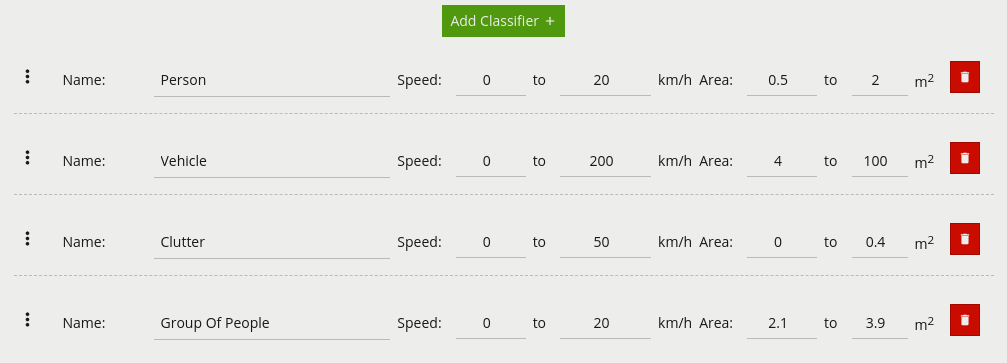
Each of the UI elements are described below:
 : Click and drag to rearrange the order of the classification groups.
To add a new classifier click the Add Classifier button  .
.
Calibration must be enabled on each channel object classification is to be used on. If not enabled, any rules that include an object filter will not trigger.
Objects are classified according to how their calibrated properties match the classifiers. Each classifier specifies a speed range and an area range. Objects which fall within both ranges of speed and area will be classified as being an object of the corresponding class.
Note: If multiple classes contain overlapping speed and area ranges then object classification may be ambiguous, since an object will match more than one class. In this case the actual classification is not specified and may be any one of the overlapping classes.
The classification data from object classification can be accessed via template tokens.
The Deep Learning Classifier is a deep learning solution designed to validate objects tracked by the Object Tracker.
When enabled, as soon as a moving object is detected, it will be evaluated by the Deep Learning Classifier and a classification and confidence level returned.
The model will return one of the following classes
The classification data from the Deep Learning Classifier can also be accessed via template tokens.
The Deep Learning Classifier can use GPU acceleration, see Deep Learning Requirements for hardware requirements.
Without GPU acceleration the Deep Learning Classifier will use the CPU, enabling the Deep Learning Classifier on multiple channels which are generating a high volume of events, (more than 1 per second) may result in poor performance of the system and is not advised.
The Deep Learning Classifier does not require the source input to have been calibrated, or the object classifier to be configured.
Classification methods (deep learning based or object based) are designed to be used independently. However, Object Classification can be used in tandem with the Deep Learning Classifier, when an appropriate rule graph is constructed. However, when using both together care should be taken. For example, as the Deep Learning Classifier is trained to detect specific objects, if custom object classes have been configured in the object classifier, e.g. small animal, the Deep Learning Classifier may erroneously filter those alerts out, as small animal is not a class the Deep Learning Classifier is trained to recognise. In these cases, use of the Deep Learning Classifier is not recommended.
By the nature of the Deep Learning Tracker’s detection methodology, every tracked object will, by definition, be classified.
For a complete list of each trackers possible classifications see trackers. The Deep Learning Trackers do not require the source input to have been calibrated,
See Deep Learning Requirements for hardware requirements for this algorithm.
Burnt-in Annotations allow VCAserver metadata to be overlaid on to the raw video stream. The burnt-in annotation settings control which VCAserver metadata is rendered into the video stream.
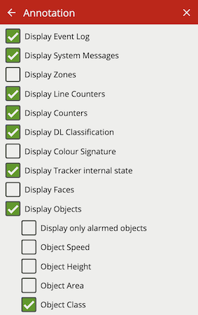
Note:
To display object parameters such as speed, height, area and classifications, the channel must first be calibrated.
To display DL Classification annotations, the channel must have an active deep learning tracker or algorithm enabled.
Some annotations only apply to certain trackers, in such cases the required tracker is listed in brackets.
Check the Display Event Log option to show the event log in the lower portion of the image.
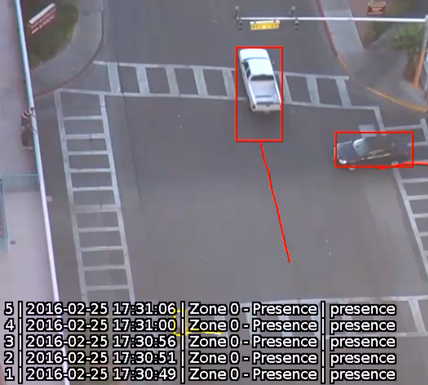
Check the Display System Messages option to show the system messages. These include Learning Scene, Tamper, Evaluation License warnings and Profile Manager status.
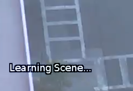
Check the Display Zones option to show the outline of any configured zones.
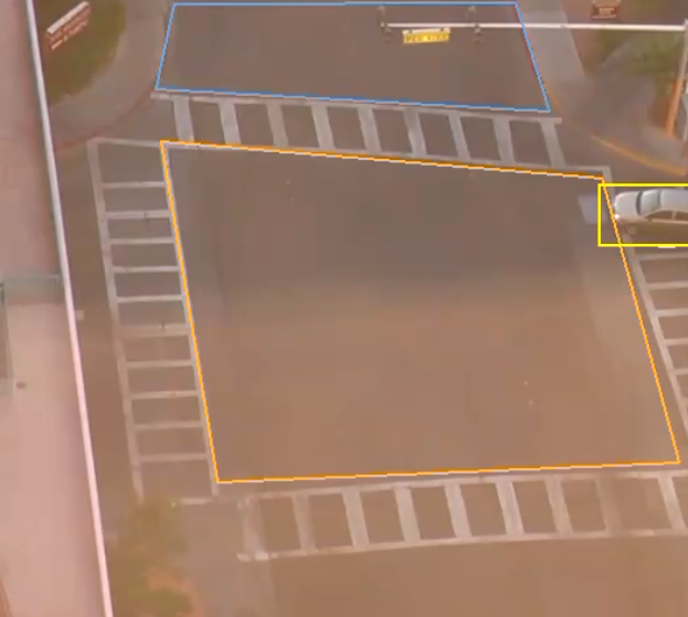
Check the Display Line Counters option to display the line counter calibration feedback information. See the Rules for more information.
Check the Display Counters option to display the counter names and values. See the Counters topic for more information.
Check the Display DL Classification option to show the class and confidence of objects evaluated by a deep learning model.
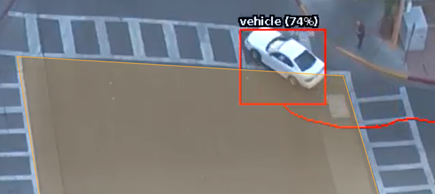
Check the Display Colour Signature option to show the current top four colours, of a possible ten, found in a given bounding box.
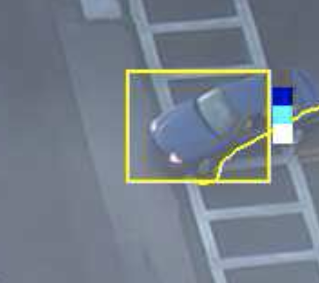
Check the Display Tracker Internal State option to visualise additional tracker annotations. These can be used to better understand how a tracker works and provide more information to configure rules. The additional annotations will change depending on the currently configured algorithms and selected tracker:
Object Tracker:
shows the total foreground pixels (fpx) within a tracked objects bounding box and the object ID (Display Objects must be enabled).
![]()
visualises the foreground pixels the object tracker is detecting in real time. Motion is represented as cyan blocks.
DL Object Tracker and DL Thermal Tracker:
shows the total pixels (px) contained within the tracked object’s bounding box and the object ID (Display Objects must be enabled).
![]()
displays grey detection boxes, illustrating when the DLOT detects an object. If Display Objects is also enabled, a bounding box may overlay the grey.
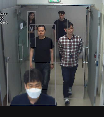
DL People Tracker:
shows the total pixels (px) contained within the tracked object’s bounding box and the object ID (Display Objects must be enabled).
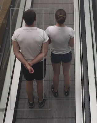
displays grey detection boxes, illustrating when the DLPT detects a person and a face. If Display Objects is also enabled, a bounding box may overlay the grey person detection. If Display Faces is also enabled, an orange bounding box may overlay the grey face detection.
DL Skeleton Tracker:
shows the total pixels (px) contained within the tracked object’s bounding box and the object ID (Display Objects must be enabled).
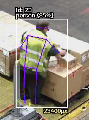
displays the body part key point metadata and grey detection boxes illustrating when the DLST detects a person. Annotations may not appear every frame and not all the body parts of a tracked person may be detected each frame. If Display Objects is also enabled, a bounding box may overlay the grey person detection.
Hand Object Interaction Tracker:
shows the total pixels (px) contained within the tracked object’s bounding box and the object ID (Display Objects must be enabled).
displays grey detection boxes, illustrating when the DLPT detects a hand or an object. If Display Objects is also enabled, a bounding box may overlay the grey detection boxes.
Face Attributes and Recognition:
shows the total pixels (px) contained within the tracked object’s bounding box and the object ID (Display Objects must be enabled).
displays grey detection boxes, illustrating when the DLPT detects a hand or an object. If Display Objects is also enabled, a yellow bounding box may overlay the grey detection boxes.
All Trackers:
![]()
![]()
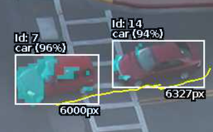
Check the Display Tamper Map option to visualise the tamper and scene change map.
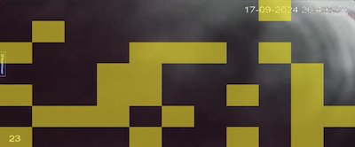
Check the Display Faces option to show face related annotations
DL Skeleton Tracker and DL People Tracker:
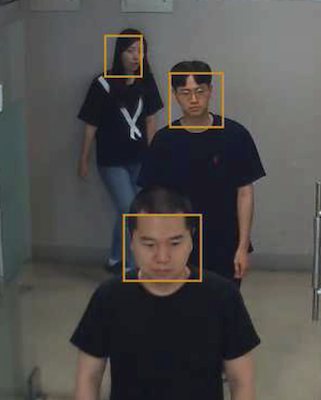
Face Attributes and Recognition:
Check the Display Accessories option to show the present or absent state of accessories for a tracked person.
Accessory Filter:
Face Attributes and Recognition:
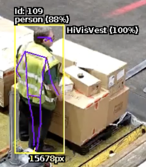
Check the Display Objects option to show the bounding boxes of tracked objects. Objects which are not in an alarmed state are rendered in yellow. Objects rendered in red are in an alarmed state (i.e. they have triggered a rule).
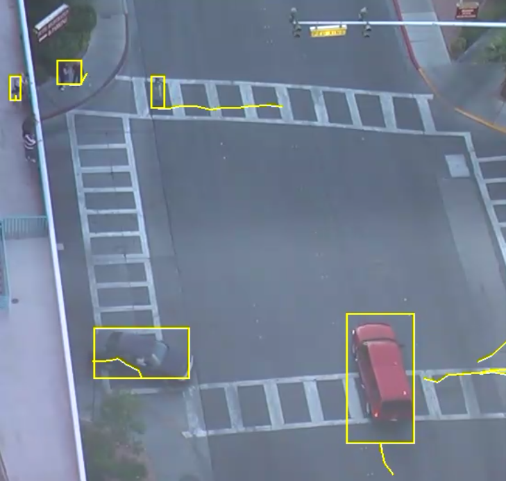
Check the Display Only Alarmed Objects option to show only bounding boxes of objects which have triggered a rule.
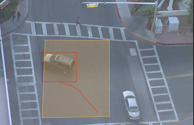
Check the Display Object Interactions option to show a tracked object’s dwell time. Dwell time is given in minutes and seconds for each zone the object is in. If a tracked object is in more than one zone, the zone name for each zone will also be displayed.
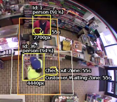
Check the Object Speed option to show the object speed.
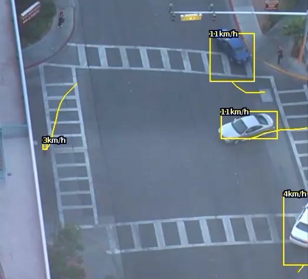
Check the Object Height option to show the object height.
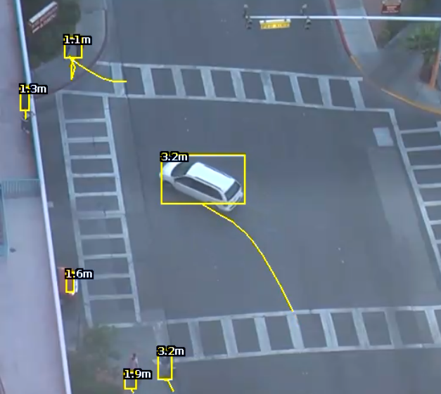
Check the Object Area option to show object area.
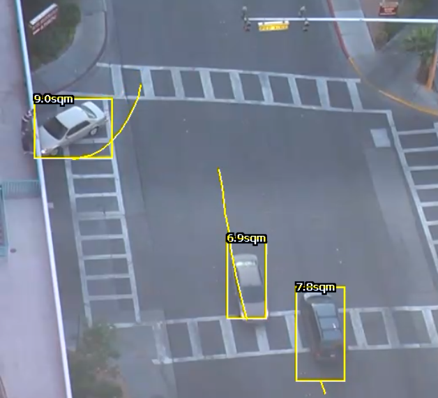
Check the Object Class to show the object Classification.
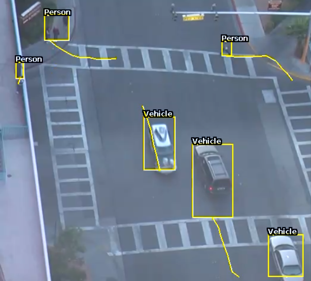
Check the Display Calibrated Position option to show the calibrated position and geographic position data. Calibrated position is given as:
X: the estimated distance (+/-) from the centre of the calibration grid in meters, where 0 is the centre of the grid.Y: the estimated distance from the camera in meters, where 0 is the camera position.Calibrated position data is only available when the channel has been calibrated
Geographic position data is the estimated latitude, longitude and elevation of a tracked object. Geographic position data is only available when the channel has been calibrated and it’s latitude, longitude, elevation and orientation has been defined.
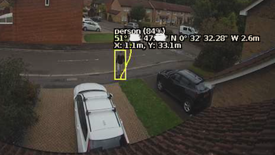
The scene change detection module resets the object tracking algorithm when it detects a large, persistent change in the image. This prevents the tracking engine from detecting image changes as tracked objects, which could be potential sources of false alarms.
The kinds of changes the scene change detection module detects are as follows:
There are 3 options for the scene change detection mode:
This is the default setting and will automatically use the recommended settings. It is recommended to use the automatic setting unless the scene change detection is causing difficulties.
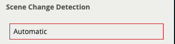
Scene change detection is disabled.
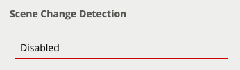
Note that when the scene change detection is disabled, gross changes in the image will not be detected. For example, if a truck parks in front of the camera the scene change will not be detected and false events may occur as a result.
Allows user configuration of the scene change detection algorithm parameters.
If automatic mode is triggering in situations where it’s not desired (e.g. it’s too sensitive, or not sensitive enough), then the parameters can be adjusted to manually control the behaviour.
In the manual mode the following settings are available:
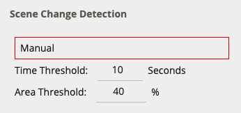
When both the time and area thresholds are exceeded the scene is considered to have changed and will be reset.
If false scene change detections are a problem, the time and/or area should be increased so that large transient changes, such as a close object temporarily obscuring the camera, do not cause false scene change detections.
When a scene change is detected, the scene is re-learnt and a message is displayed in the event log and annotated on the video
![]()
The video preview menu provides information on the channel view currently open.
The Video Status is a UI overlay that presents real time information on the channel view currently open. Importantly, this is not a burnt-in annotation, the provided information is not visible in the RTSP stream for this channel.
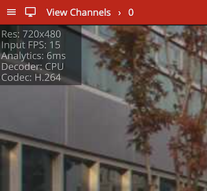
Statistics included in this overlay are:
Resolution / Original: Input video resolutionCropped: The video resolution with the crop applied (only visible when a crop is applied)Input FPS: Input video frame rate defined by the stream (e.g. 15) or estimated internally (15*)Analytics: Length of time taken to run the configured analytics (e.g. the trackers and rules configured).Decoder: The hardware used to decode the image (either CPU, VAAPI, NVIDIA)Codec: The video codec used by the input videoThe video adjustments menu provides options for transforming the input video source.
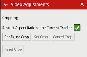
Cropping allows for the field of view of the input video to be focused on a specific area. This ensures that only relevant areas of the field of view is passed to the tracker algorithm, in certain cases this can improve detection range and reduce false positives.
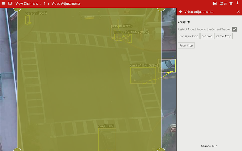
Restrict Aspect Ratio to the Current Tracker: When enabled, limits the region of interest to the aspect ratio matching the input for the currently selected tracker’s deep learning model. Further reduces any superfluous letter boxing or artifacts generated by rescaling the input image.
Configure Crop: Enables a configurable region of interest zone on the input image which represents the eventual crop.
Set Crop: After selecting Configure Crop and defining the region of interest, selecting Set Crop will apply the crop to the input image and reinitialize the channel.
Cancel Crop: Cancels the process of configuring the crop.
Reset Crop: Once a crop region of interest has been configured and set, Reset Crop will remove the defined crop, allowing it to be redefined.
The system settings page facilitates administration of system level settings such as network configuration, and authentication.
The network configuration of the device can be changed in the network settings configuration section:
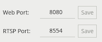
Web Port: Sets the port that the device’s web server will listen on. The Save button must be clicked to apply the change.
RTSP Port: Sets the port that the device’s RTSP server will listen on. The Save button must be clicked to apply the change.
The VCAserver web server that hosts the UI, the REST API and the SSE metadata streams, by default is unencrypted using HTTP. To secure these connections, SSL can be enabled allowing for a self managed end to end encrypted connection between your browser and the back end services.
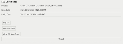
Once a certificate (.pem) and key (.key) files is uploaded, the web server will switch to HTTPs and provide a link to the new URL for the user to follow.

On specific platforms, the network settings for the host system is exposed to allow configuration of the network devices.
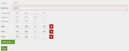
On specific platforms, the time zone can be selected and the time settings for the host system can be configured (manually or via NTP server).
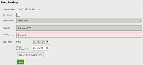
The system information section shows the Uptime of VCAserver (how long the application has been running without restarting) as well as the device CPU and Memory usage:
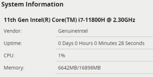
The GPU devices section shows information on all the detected graphics processing units. Name and vendor information are provided for reference, with the current temperature, overall utilisation and memory usage:
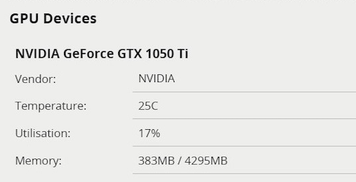
These values, combined with the system information, can be used to determine if the current configuration is overly stressing the available hardware.
VCAserver can be protected against unauthorised access by enabling authentication. By default, authentication is enabled and the default credentials must be entered when accessing the device for the first time. Authentication applies to all functions including the web interface and API, RTSP server and discovery interfaces.
Click the Enable button to enable authentication.
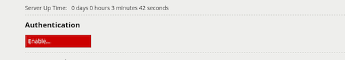
The password must be confirmed before authentication can be enabled, in order to prevent the user being locked out of the device.
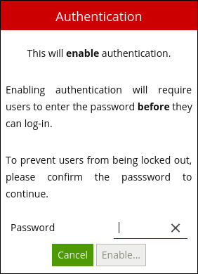
Click the Change Password button to change the password.
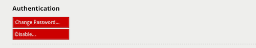
Enter the new password, and confirm the current password in order to apply the changes.
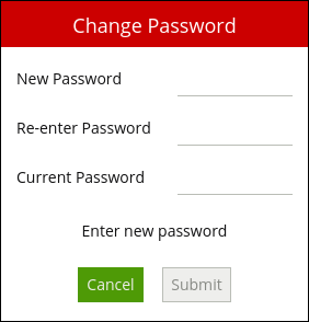
WARNING: If the password is forgotten, the device will not be accessible. The only way to recover access to a device without a valid password is to perform a physical reset, as described in the Forgotten Password section.
Click the Disable button to disable authentication and allow users to access the device without entering a password. The password is required to disable authentication.
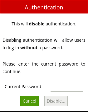
The default credentials are as follows:
Username: admin
Password: admin
If a system becomes inaccessible due to a lost password, the only way to recover access to the device is to delete the configuration file VCAserver is using. This process differs between platforms:
C:\VCACore\configuration/var/opt/VCA-Core/Under configuration, buttons to allow the management of VCAserver’s configuration are provided:
Import Configuration: Allows the import of a previously saved configuration file.
Export Configuration: Exports the current configuration to a file config.json
Reset to Default Configuration: removes all configured channels, rules, actions etc, resetting VCAserver to the default state
Current version information is also provided.
VCAserver produces metadata accessible though various APIs but also through the action’s token system. One aspect of that metadata is the X and Y coordinates for objects in a camera view.
Under the metadata section, the definition of aspects of this metadata can be specified:
Normalised coordinate range maximum: The value representing the right hand side of the screen. For example can be set to 100 to signify location as a percentage of the field of view
Flip Y axis coordinates: The ability specify the meaning of 0 in the Y axis, changing it from the top of the field of view to be the bottom.
Round coordinates to nearest integer: The ability to round a given coordinate to the nearest whole number. This should be used with care especially in cases where the normalised coordinate range maximum has been set to a low value.
VCAserver is able to embed Base64 encoded JPEG snapshots of tracked objects as part of the SSE metadata stream. When enabled all objects detected across all channels will start to have JPEG encoded snapshots generated, whether the SSE metadata is being used or not. In scenes with many objects or deployments with many channels, this setting will have an impact on the CPU and memory usage.
Enabled: When checked, snapshots of the object are added to the SSE metadata stream updated at the specified interval.
Interval: Defines how often the JPEG snapshot of an object is updated.
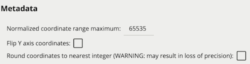
The units used in burnt-in annotation for speed, height and area. Does not affect the input UI for rules e.g. speed filter.
An internal ONVIF service allowing for VCAserver’s RTSP video and compliant event data to be accessed using the ONVIF standards.
If digital inputs are available, the input sensors can be configured in two different modes:
Relay: Enables the pull-up resistor, for use when inputs are connected to switches.
Voltage: Disables the pull-up resistor.
The support page provides a repository for tools which can be utilised to help debug issues.
The Logs section provides a list of download links to the currently available logs. Logs are user-readable text files which log VCAserver messages. These logs can be submitted to the VCA Technology support staff to help resolve issues. New log files are created when VCAserver is started. If a log file reaches a certain size then it will be split into separate files.
The list of log files can be reloaded using the Reload Logging data button. Only a limited number of files can be stored with the oldest being replaced if that storage limit is met.
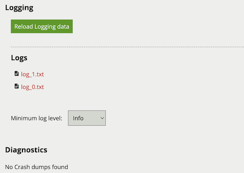
The minimum log level defines the granularity of log entries based on a hierarchy of logging messages. Each selected level will include messages from the level above, where Fatal will have the fewest and only most severe messages and Trace including every log message available.
| Logging Level |
|---|
| Fatal |
| Error |
| Warning |
| Info |
| Debug |
| Trace |
The Diagnostics section provides a list of download links to the currently available crash dumps. These crash dumps can be uploaded to the VCA Technology support staff to provide more in depth system state information.
The list of core dump files can be reloaded using the Reload Logging data button. Only a limited number of files can be stored, with the oldest being replaced if that storage limit is met.
VCAserver can be set up to perform a specific action when an analytic event occurs. Examples include sending an email, TCP or HTTP message to a server.
VCAserver allows templated messages to be written for email, TCP and HTTP actions which are automatically filled in with the metadata for the event. This allows the details of the event to be specified in the message that the action sends, e.g. the location of the object, type of event, etc.
The templating system uses mustache, which is widely used and well-documented online. A brief overview of the templating syntax will be provided here. Templated messages can be written by using tokens in the message body. For example:
Hello {{name}}!is a template with a name token. When the template is processed, the event metadata is checked to see if it has a name entry. If it does, the {{name}} token is replaced with the name of the event. If it isn’t present, the token will be replaced with blank space.
If an event with the name Presence occurs, the processed template will be Hello Presence! but if it doesn’t have a name, it will be Hello !
Some tokens may also have sub-properties which can be accessed as follows:
It happened at {{start.hours}}!Tokens can also be evaluated as boolean values, allowing simple conditional statements to be written:
{{#some_property}}Hello, world!{{/some_property}}In this example, if some_property is present in the event metadata, then “Hello, world!” will appear in the message. Otherwise, nothing will be added to the message.
If some_property is a boolean, then its value will determine whether or not the conditional is entered. If some_property is an array property, it will only evaluate as true if the array is not empty.
Finally, tokens can also be arrays which can be iterated over. For example:
{{#object_array}}
{{name}} is here!
{{/object_array}}
This template will iterate through each item in object_array and print its name, if it has a name property. For example, the array [{"name": "Bob"}, {"name": "Alice"}, {"name": "Charlie"}] will result in the following output:
Bob is here!
Alice is here!
Charlie is here!Lower case names represent tokens that can be used with the {{token}} syntax. These tokens are generic to all events and will always be present in any given event and resulting action. Upper case names represent boolean or array properties that should be used with the {{#token}}...{{/token}} syntax. These tokens tend to represent metadata objects that are specific to certain event types.
The name of the event
The unique id of the event
The type of the event. This is usually the type of rule that triggered the event
This is a boolean property that allows conditionals to be performed on the given type name.
For example, to print something only for events of type “presence”:
{{#type.presence}}My text{{/type.presence}}The start time of the event. It has the following sub-properties:
start.iso8601start.yearstart.monthstart.daystart.hoursstart.minutesstart.secondsstart.millisecondsstart.microsecondsstart.nanosecondsstart.epochstart.offset.signstart.offset.hoursstart.offset.minutesThe iso8601 property is a date string in the ISO 8601 format.
The offset property is the time zone offset.
The end time of the event. Same properties as {{start}}
The hostname of the device that generated the event
The IP address of the device that generated the event
The armed state of VCAserver. It has the following sub-properties:
armed: The armed state of VCAserver when the event was triggeredExample:
{{#Armed}}
Armed State: {{armed}}
{{/Armed}}Properties of the channel that the event occurred on. It has the following sub-properties:
id: The id of the channel that the event occurred onname: The name of the channel that the event occurred ondescription: The description of the channel that the event occurred onExample:
{{#Channel}}
Channel ID: {{id}}
Channel Name: {{name}}
Channel Description: {{description}}
{{/Channel}}An array of the zones associated with the event. It has the following sub-properties:
id: The id of the zonename: The name of the zonechannel: The id of the channel the zone is attached tocolour: The RGBA colour of the zonedetection: 0 if the zone is non-detection zone, 1 otherwisetype: 0 for a closed polygon, 1 for a lineoutline: The outline of the zoneThe outline of a zone has the following sub-properties:
outline.rect.top_left.x: x-coordinate of the top left corneroutline.rect.top_left.y: y-coordinate of the top left corneroutline.rect.bottom_right.x: x-coordinate of the bottom right corneroutline.rect.bottom_right.y: y-coordinate of the bottom right cornerExample:
{{#Zone}}
id: {{id}}
name: {{name}}
channel:{{channel}}
colour: ({{colour.r}}, {{colour.g}}, {{colour.b}}, {{colour.a}})
{{/Zone}}An array of the objects that triggered the event. It has the following sub-properties:
id: The id of the objectoutline: The outline of the objectwidth: The width of the bounding box based on the outlineheight: The height of the bounding box based on the outlineThe bounding box outline of an object has the following sub-properties:
outline.rect.top_left.x: x-coordinate of the top left corneroutline.rect.top_left.y: y-coordinate of the top left corneroutline.rect.bottom_right.x: x-coordinate of the bottom right corneroutline.rect.bottom_right.y: y-coordinate of the bottom right cornerUsing a combination of these four coordinates, any corner of an object’s bounding box can be obtained.
Example:
{{#Object}}
id: {{id}}
width: {{width}}
height: {{height}}
Top left corner: ({{outline.rect.top_left.x}}, {{outline.rect.top_left.y}})
{{/Object}}An array of line counter counts. It has the following sub-properties:
rule_id: The id of the line counter rulewidth: The calibration width of the line counterposition: The position at which the object crossed the linecount: The number of objects that crossed the linedirection: The direction in which the object(s) crossed the line. 0 for A, 1 for BExample:
{{#CountingLine}}
rule_id: {{rule_id}}
calibration width: {{width}}
position: {{position}}
count: {{count}}
direction: {{direction}}
{{/CountingLine}}An array of counter or occupancy counts. It has the following sub-properties:
id: The id of the countername: The name of the countervalue: The number of countsdifference: The difference in count value since eventExample:
{{#Counter}}
id: {{id}}
name: {{name}}
count: {{value}}
difference: {{difference}}
{{/Counter}}The estimated area of the object. This token is a property of the object token. It is only produced if calibration is enabled. It has the following sub-properties:
value: The estimated area of the objectExample:
{{#Object}}{{#Area}}{{value}}{{/Area}}{{/Object}}The estimated position relative to the camera. value.x is the estimated distance (+/-) from the centre of the calibration grid in meters, where 0 is the centre of the grid. value.y is the estimated distance from the camera in meters, where 0 is the camera position. This token is a property of the object token. It is only produced if calibration is enabled. It has the following sub-properties:
value: The estimated area of the objectExample:
{{#Object}}{{#CalibratedPosition}}
X: {{value.x}}
Y: {{value.y}}
{{/CalibratedPosition}}{{/Object}}The estimated geographic position relative to the given longitude, latitude, elevation and orientation of the camera. This token is a property of the object token. It is only produced if calibration is enabled and the camera’s longitude, latitude, elevation and orientation are set. It has the following sub-properties:
value.longitude: is the estimated longitude of the object.value.latitude: is the estimated latitude of the object.value.elevation: is the estimated elevation of the object.{{#Object}}{{#GeoLocation}}
Latitude: {{value.latitude}}
Longitude: {{value.longitude}}
Elevation: {{value.elevation}}
{{/GeoLocation}}{{/Object}}The classification of the object. This token is a property of the object token. It is only produced if calibration is enabled. It has the following sub-properties:
value: The classification of the objectExample:
{{#Object}}{{#Classification}}{{value}}{{/Classification}}{{/Object}}The classification generated by a deep learning model (e.g. Deep Learning Classifier or Deep Learning Object Tracker). This token is a property of the object token. The algorithm must be enabled in order to produce this token, but calibration is not required. It has the following sub-properties:
class: What the object has been classified as (person, vehicle)confidence: A value between 0.0 and 1.0 representing the confidence of the classification (0.0 least confident, 1.0 most confident)Example:
{{#Object}}{{#DLClassification}}
Class: {{class}}
Confidence: {{confidence}}
{{/DLClassification}}{{/Object}}The face generated by a deep learning model. This token is a property of the object token. The Deep Learning Skeleton Tracker must be enabled in order to produce this token. The face should only be present when the person is looking towards the camera. It has the following sub-properties:
outline: The outline of the faceThe bounding box outline of a face has the following sub-properties:
outline.rect.top_left.x: x-coordinate of the top left corneroutline.rect.top_left.y: y-coordinate of the top left corneroutline.rect.bottom_right.x: x-coordinate of the bottom right corneroutline.rect.bottom_right.y: y-coordinate of the bottom right cornerExample:
{{#Object}}{{#Face}}
Outline: ({{#outline}}{{rect.top_left.x}}, {{rect.top_left.y}}), ({{rect.bottom_right.x}}, {{rect.bottom_right.y}}{{/outline}})
{{/Face}}{{/Object}}The current stats of the GPU device (only populated when action is triggered by a system source)
utilisation: The current GPU utilisation{{#GpuStats}}{{utilisation}}{{/GpuStats}}The estimated position of the object. This token is a property of the object token. It is only produced if calibration is enabled. It has the following sub-properties:
value.x: The estimated normalised x-axis position of the objectvalue.y: The estimated normalised y-axis position of the objectExample:
{{#Object}}{{#GroundPoint}}Position: ({{value.x}}, {{value.y}}){{/GroundPoint}}{{/Object}}The Head generated by a deep learning model. This token is a property of the object token. The Deep Learning Skeleton Tracker or the Deep Learning People Tracker must be enabled in order to produce this token. It has the following sub-properties:
outline: The outline of the headThe bounding box outline of a head has the following sub-properties:
outline.rect.top_left.x: x-coordinate of the top left corneroutline.rect.top_left.y: y-coordinate of the top left corneroutline.rect.bottom_right.x: x-coordinate of the bottom right corneroutline.rect.bottom_right.y: y-coordinate of the bottom right cornerExample:
{{#Object}}{{#Head}}
Outline: ({{#outline}}{{rect.top_left.x}}, {{rect.top_left.y}}), ({{rect.bottom_right.x}}, {{rect.bottom_right.y}}{{/outline}})
{{/Head}}{{/Object}}The estimated height of the object. This token is a property of the object token. It is only produced if calibration is enabled. It has the following sub-properties:
value: The estimated area of the objectExample:
{{#Object}}{{#Height}}{{value}}{{/Height}}{{/Object}}The observable that triggered the event.
id: The ID of the observable that triggered the eventExample:
{{#Observable}}{{id}}{{/Observable}}The total pixels (px) contained within the tracked object’s bounding box. This value is relative to the channels input source resolution, e.g. the value will change for the same object, in the same scene if the resolution was different. This token is a property of the object token. It has the following sub-properties:
value: The number of pixels in the bounding boxExample:
{{#Object}}{{#Pixels}}{{value}}{{/Pixels}}{{/Object}}The estimated speed of the object. This token is a property of the object token. It is only produced if calibration is enabled. It has the following sub-properties:
value: The estimated speed of the objectExample:
{{#Object}}{{#Speed}}{{value}}{{/Speed}}{{/Object}}The text data detected and associated with an object. This token is a property of the object token. It has the following sub-properties:
value: Text data detected and associated with this objectExample:
{{#Object}}{{#Text}}
Object Text: {{value}}
{{/Text}}{{/Object}}The colour signature of the object. This token is a property of the object token. It has the following sub-properties:
colour_name: Descriptive name of colour e.g. ‘red’proportion: The percentage of an object that is made up of the specified colourExample:
{{#Object}}{{#ColourSignature}}
{{#colours}}
Colour: {{colour_name}}, Proportion: {{proportion}}
{{/colours}}
{{/ColourSignature}}{{/Object}}The colour signature for each segment of a Person. This token is a property of the object token. It is only produced if the object has a classification of Person. It has the following sub-properties:
segments: Provides a Colour Signature for the segment of the person object (either torso or legs)Example:
{{#Object}}
{{#SegmentedColourSignature}}
{{#segments.torso}}
Torso:
{{#colours}}
Colour: {{colour_name}}, Proportion: {{proportion}}
{{/colours}}
{{/segments.torso}}
{{#segments.legs}}
Legs:
{{#colours}}
Colour: {{colour_name}}, Proportion: {{proportion}}
{{/colours}}
{{/segments.legs}}
{{/SegmentedColourSignature}}
{{/Object}}The following is an example of a template using most of the available tokens:
Event #{{id}}: {{name}}
Event type: {{type.string}}
Start time (ISO 8601 format): {{start.iso8601}}
End time:
day: {{end.day}}
time: {{end.hour}}:{{end.minutes}}:{{end.seconds}}.{{end.microseconds}}
Device: {{host}}
Channel: {{#Channel}}{{id}}{{/Channel}}
{{#type.presence}}
{{#Object}}
Object ID: {{id}}
{{#Classification}}Object Classification: {{value}}{{/Classification}}
{{#Height}}Object Height: {{value}}m{{/Height}}
Object bounding box: [
  ({{outline.rect.top_left.x}}, {{outline.rect.top_left.y}}),
  ({{outline.rect.bottom_right.x}}, {{outline.rect.top_left.y}}),
  ({{outline.rect.bottom_right.x}}, {{outline.rect.bottom_right.y}}),
  ({{outline.rect.top_left.x}}, {{outline.rect.bottom_right.y}})
]
{{/Object}}
{{/type.presence}}

{{#Counter}}
Counter triggered.
id: {{id}}
name: {{name}}
count: {{count}}
{{/Counter}}

{{#LineCounter}}
rule_id: {{rule_id}}
calibration width: {{width}}
position: {{position}}
count: {{count}}
direction: {{direction}}
{{/LineCounter}}
In this example, the object information is only printed for events of type “presence”.
This template might result in the following message:
Event #350: My Bad Event
Event type: presence
Start time (ISO 8601 format): 2017-04-21T10:09:42+00:00
End time:
day: 21
time: 10:09:42.123456
Device: mysecretdevice
Channel: 0

Object ID: 1
Object Classification: Person
Object Height: 1.8m
Object bounding box: [
  (16000, 30000),
  (32000, 30000),
  (32000, 0),
  (16000, 0)
]

Counter triggered.
id: 10
name: My Counter
count: 1

rule_id: 350
calibration width: 1
position: 1
count: 1
direction: 0VCAserver supports an RTSP server that streams annotated video in RTSP format.
The RTSP URL for channels on a VCA device is as follows:
rtsp://\<device ip\>:8554/channels/\<channel id\>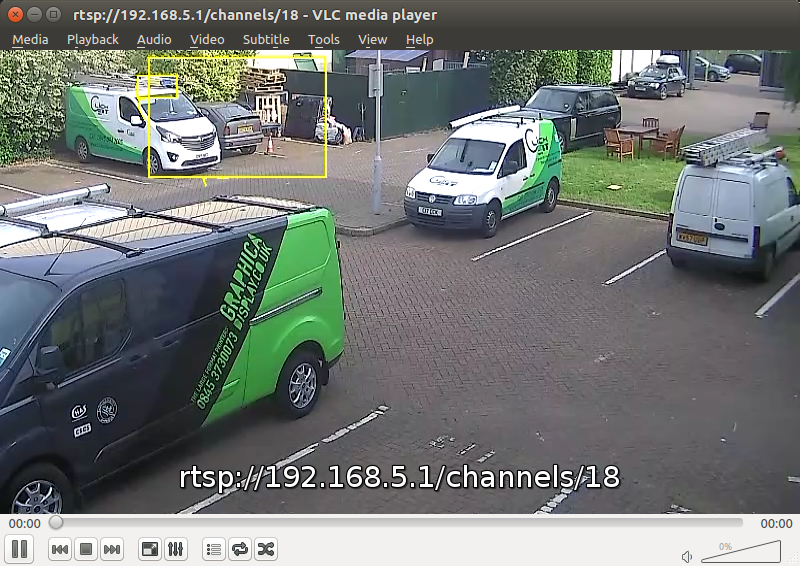

VCAserver supports the notification of events with annotated snapshots and streaming of real-time annotated video to Sureview Immix.
The following ports need to be accessible on the VCA device (i.e. a VCAbridge or an instance of VCAserver) from the Immix server:
The first step is to add the VCA device.
In the Immix site configuration tab, click Manage Devices and Alarms, then Add Device:
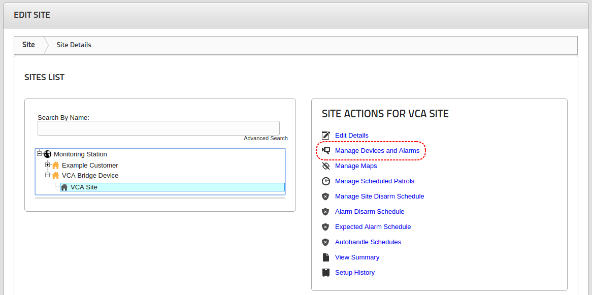
On the Add Device page, set the following options:
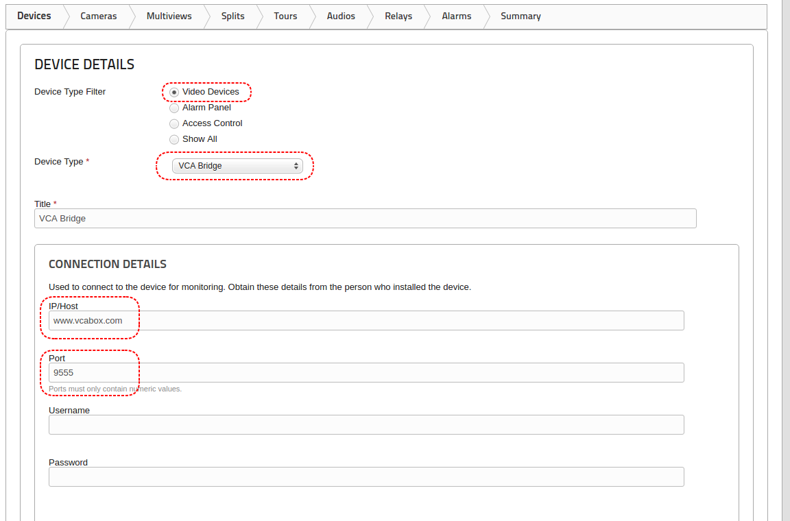
Once the device has been added, channels from the VCA device can be added.
Note: Immix currently supports only one VCA channel per device. To support more channels, simply add more devices.
Click the Cameras tab and Add a Camera to add a new channel:
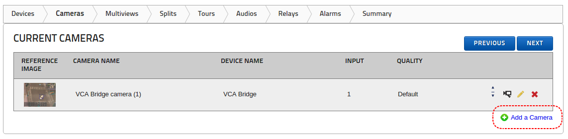
On the Camera Details page set the following options:
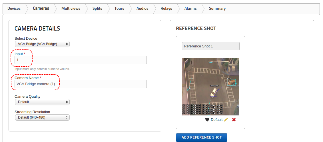
In order to set the Input value correctly in Immix, the following steps should be followed:
CHANNEL ID
| Channel Id in VCA | Input in Immix |
|---|---|
| 0 | 1 |
| 1 | 2 |
| 2 | 3 |
| 5 | 6 |
| 100 | 101 |
The reason that the Immix Input is 1 higher than the VCA channel Id is that Immix uses one-based inputs but VCA uses zero-based channel Ids.
Generating a summary provides a single document with all of the details necessary to configure the VCA device. Click the Summary tab and a PDF report is created:
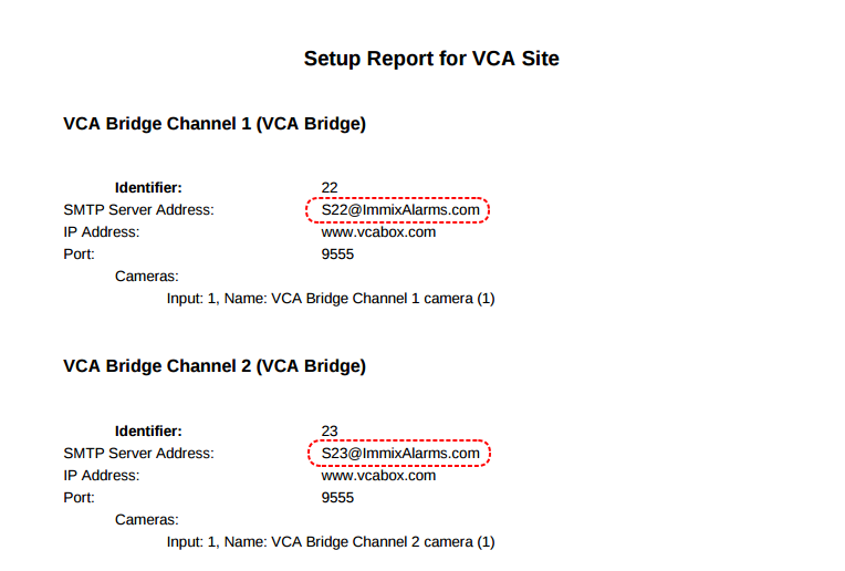
Make a note of the email addresses highlighted in red. These email addresses need to be entered in the VCA device configuration (see next section).
Once a device and camera are configured in Immix, the email addresses generated as part of the summary need to be added to the VCAserver configuration.
VCAserver notifies Immix of events via email, so each channel configured for Immix needs to have an email action configured. For more details on how to configure Actions or Sources see the corresponding topics.
Add an Email action with the following configuration:
Once this is done, add the correct source to the email action.
The event types reported in the VCAserver interface are slightly different to the event types reported in the Immix client. The events are mapped as follows:
| Event in VCA | Event in Immix |
|---|---|
| Presence | Object Detected |
| Enter | Object Entered |
| Exit | Object Exited |
| Appear | Object Appeared |
| Disappear | Object Disappeared |
| Stopped | Object Stopped |
| Dwell | Object Dwell |
| Direction | Object Direction |
| Speed | Object Speed |
| Tailgating | Tailgating |
| Tamper | Tamper Alarm |
VCAserver has inbuilt support for a subset of ONVIF profile S and Profile M endpoints. To date, these provide the following functions using the ONVIF interface:
More detail on each ONVIF function is given below, screenshots are provided using the ONVIF Device Manager implementation varies application to application.
ONVIF device discovery retrieves information about the ONVIF enabled device including the following data:
VCATechnology
The above image shows the ONVIF Device Manager’s Identification interface with a VCAserver instance running on 192.168.0.23 (authentication disabled). Some of these Identification Variables are configurable, see Redistribution for more information.
VCAserver supports an RTSP server that streams annotated video in RTSP format. These streams are also discoverable through ONVIF.
The ONVIF events service allows a third-party application to pull a list of events from the VCAserver platform. An event is defined as any logical rule, with Can Trigger Actions enabled, or Other Source, such as interval or DI, which triggers. Neither the logical rule nor the Other Source has to be configured with an action, to be included within ONVIF event service cache.
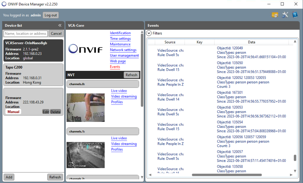
The ONVIF Device Manager’s Events interface with a VCAserver instance running on 192.168.50.65 (authentication disabled), where the data component of each event is populated with the above properties.
The ONVIF metadata service allows the streaming of object metadata from the VCAserver platform. Currently supported object metadata include: Bounding box, ground point, object classification and speed.
Due to the nature of VCAserver as an application, a number of mandatory Profile M and S features are not supported.
A media profile and the relevant pre-defined configurations are provided for each channel that is configured in VCAserver. This profile configuration is defined by the channel source and is therefore not configurable.
VCAserver only supports a single user so user creation is not supported. Modifying the password is not currently possible via ONVIF.
It is currently possible to get the network information via ONVIF, but not to make changes.
Device Manager is a third-party, open source windows application available at ONVIF Device Manager. Due to the age of the application, only basic discovery is supported within this application unless the authentication in the VCAserver UI is disabled, in which case, RTSP streams and the events will be visible within ODM.
If you require more information on ONVIF profiles please refer to the ONVIF documentation.